Continue to Site

Welcome to our site!

Electro Tech is an online community (with over 170,000 members) who enjoy talking about and building electronic circuits, projects and gadgets. To participate you need to register. Registration is free. Click here to register now.

  • Welcome to our site! Electro Tech is an online community (with over 170,000 members) who enjoy talking about and building electronic circuits, projects and gadgets. To participate you need to register. Registration is free. Click here to register now.

How to decrease the output current and voltage from this DC to DC converter?

Status
Not open for further replies.
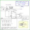
My AC electrical voltage is regulated very well so I could use a 9VDC/500mA wall-wart to power an LM317 8.4V/300mA power supply.
When the current reaches about 300mA then the output of the wall-wart drops to 10.2V which is the input dropout voltage of the regulator that limits the output current.

I did not use a series output diode because my electricity is very reliable and rarely fails.

The circuit does not detect a full charge then disconnect the battery because I DOO DAT.

You know what? Many times I discharged the batteries too low. Then I let them rest and cool then I discharged them even more.
The charger never caused them to catch on fire so I am lucky.
 

Attachments

  • LM317 8.4V-500mA power supply-charger.png
    LM317 8.4V-500mA power supply-charger.png
    21.1 KB · Views: 726
Hi,

I would be very very careful when trying to use an output series diode to prevent battery back discharge into the charger. That is of course because then we have to rely on the diode voltage drop being constant in order to set the output voltage to the correct level. If the diode voltage drops, the output increases.

One idea that is sometimes used is to wire in the contacts of a relay in series with the battery. The relay coil is driven from the input voltage source, so if the source goes away the relay contacts open and the battery is disconnected completely. The relay coil is chosen based on the lowest level input that will properly run the charger so that it will open long before the charger starts to malfunction.

Another idea would be to wire the diode into the ground circuit and use an op amp voltage follower to track the B- battery voltage for the LM317. We would have to make sure though that the op amp input does not draw current when the LM317 no longer can supply power to the circuit. Of course this complicates the circuit though.
 
Last edited:
Hi,

I would be very very careful when trying to use an output series diode to prevent battery back discharge into the charger. That is of course because then we have to rely on the diode voltage drop being constant in order to set the output voltage to the correct level. If the diode voltage drops, the output increases.

One idea that is sometimes used is to wire in the contacts of a relay in series with the battery. The relay coil is driven from the input voltage source, so if the source goes away the relay contacts open and the battery is disconnected completely. The relay coil is chosen based on the lowest level input that will properly run the charger so that it will open long before the charger starts to malfunction.

Another idea would be to wire the diode into the ground circuit and use an op amp voltage follower to track the B- battery voltage for the LM317. We would have to make sure though that the op amp input does not draw current when the LM317 no longer can supply power to the circuit. Of course this complicates the circuit though.
Hi again,

- If I used two cells in series to charge through your circuit then I should have to use double voltage (8.4V) and double current (0.7A per cell X 2= 1.4A). And also, need double current (0.7X2= 1.4A) but same voltage (4.2V) to charge two cells in parallel, am I right?

- Are there any circuit in your hand which indicates when charging current level is lower than 5mA OR, when charging voltage tends to reach 4.2V? It would be a nice 'battery fully charged' monitor, isn't it?
 
If I used two cells in series to charge through your circuit then I should have to use double voltage (8.4V) and double current (0.7A per cell X 2= 1.4A). And also, need double current (0.7X2= 1.4A) but same voltage (4.2V) to charge two cells in parallel, am I right?
No, no and no.
Lithium cells are dangerous if over-charged so they are not charged in series. A balancing charger is used that effectively charges each cell separately to 4.20V each.
The current is not doubled in a series circuit because the same current flows in everything.

If you charge two cells in parallel then one cell might draw too much charging current and the other cell will not get enough charging current. I have a cell phone battery that has two cells welded in parallel. The cells must be selected to be identical.

Are there any circuit in your hand which indicates when charging current level is lower than 5mA OR, when charging voltage tends to reach 4.2V? It would be a nice 'battery fully charged' monitor, isn't it?
A comparator is used to compare the voltage across a series resistor with a low voltage then Ohm's Law determines the amount of current.
A charging Lithium cell reaches 4.2V long before it is fully charged.
 
Hi again,

- If I used two cells in series to charge through your circuit then I should have to use double voltage (8.4V) and double current (0.7A per cell X 2= 1.4A). And also, need double current (0.7X2= 1.4A) but same voltage (4.2V) to charge two cells in parallel, am I right?

- Are there any circuit in your hand which indicates when charging current level is lower than 5mA OR, when charging voltage tends to reach 4.2V? It would be a nice 'battery fully charged' monitor, isn't it?

Hi,

As audioguru mentioned, there are problems that come up when charging in series or parallel. The series problem is that of voltage sharing, and the parallel problem is that of current sharing.

Commercial chargers will do this by monitoring each cell individually and halting the charge on any cell that gets fully charged. For a hobby charger we'd have to build that functionality into it, but it's not as simple as just hooking two in series or two in parallel.

In theory if the two cells were exactly the same at all times then we could do that, but we dont really know if they are the same at all times because their characteristics change over time and charge state. This is why i never recommend charging in series or parallel. There are people that do it, but it's kind of dangerous because if something does wrong it's fire and smoke on the way.

So the best bet is to simply build two chargers if you need to charge two cells. These chargers are so cheap to build it cant possibly hurt to build two. That wey each cell is assured of being charged safely.

Yes we can add a charge termination monitor that lights an LED. It should monitor charge current really because for a proper charger the voltage is already monitored by the charge circuit itself. Once the charge current gets down to a small percentage of the normal current level, we can light an LED.
This would not be hard to add and if you like i can add one or you could come up with your own idea. My first idea is to use a simple comparator and sense resistor to monitor the charge current, or if you dont mind a little less accurate we could use a simple transistor and sense resistor where when the current got low the LED would turn off (a little more circuitry and it would turn on if that's what you really want).

I am going to redraw my original circuit anyway so i'll add a charge monitor to it. I have another circuit too that has a charge monitor. There's a slight change to the original circuit that can make it work better so i'll show that too.

LATER:
I have redrawn the schematic to show the more correct connection for the adjustment resistors. Note that this one has the resistor R3 connected to the sense resistor R4 instead of directly to ground. That's the correct way to do it. It will work the other way too, but will take longer to charge to the full level.
I'll see about adding the charger termination sense next.

One quick note...
When measuring the cell voltage it must be measured right across the cell because with this charger the negative terminal of the cell does not connect to ground. Also, the input voltage must be slightly higher because the sense resistor takes about 0.6v, and that means the output of the LM317 (shown here as another similar IC) will be higher than 4.2v when the cell is fully charged although the cell voltage is really 4.2v.
Of course the better max cell voltage setting is 4.15v though.
 

Attachments

  • PowerSupplyForLi-Ion-02.gif
    PowerSupplyForLi-Ion-02.gif
    25.9 KB · Views: 456
Last edited:
Hi,

As audioguru mentioned, there are problems that come up when charging in series or parallel. The series problem is that of voltage sharing, and the parallel problem is that of current sharing.

Commercial chargers will do this by monitoring each cell individually and halting the charge on any cell that gets fully charged. For a hobby charger we'd have to build that functionality into it, but it's not as simple as just hooking two in series or two in parallel.

In theory if the two cells were exactly the same at all times then we could do that, but we dont really know if they are the same at all times because their characteristics change over time and charge state. This is why i never recommend charging in series or parallel. There are people that do it, but it's kind of dangerous because if something does wrong it's fire and smoke on the way.

So the best bet is to simply build two chargers if you need to charge two cells. These chargers are so cheap to build it cant possibly hurt to build two. That wey each cell is assured of being charged safely.

Yes we can add a charge termination monitor that lights an LED. It should monitor charge current really because for a proper charger the voltage is already monitored by the charge circuit itself. Once the charge current gets down to a small percentage of the normal current level, we can light an LED.
This would not be hard to add and if you like i can add one or you could come up with your own idea. My first idea is to use a simple comparator and sense resistor to monitor the charge current, or if you dont mind a little less accurate we could use a simple transistor and sense resistor where when the current got low the LED would turn off (a little more circuitry and it would turn on if that's what you really want).

I am going to redraw my original circuit anyway so i'll add a charge monitor to it. I have another circuit too that has a charge monitor. There's a slight change to the original circuit that can make it work better so i'll show that too.

LATER:
I have redrawn the schematic to show the more correct connection for the adjustment resistors. Note that this one has the resistor R3 connected to the sense resistor R4 instead of directly to ground. That's the correct way to do it. It will work the other way too, but will take longer to charge to the full level.
I'll see about adding the charger termination sense next.

One quick note...
When measuring the cell voltage it must be measured right across the cell because with this charger the negative terminal of the cell does not connect to ground. Also, the input voltage must be slightly higher because the sense resistor takes about 0.6v, and that means the output of the LM317 (shown here as another similar IC) will be higher than 4.2v when the cell is fully charged although the cell voltage is really 4.2v.
Of course the better max cell voltage setting is 4.15v though.
I am sorry because in various ideas of your here I lost my sense and confused what you modified recently... My be recently you edited 'better charger than before'. But I think it has no auto-termination feature. It has no monitor indicator too.

I wish simple circuit with transistors (but I have two pieces of LM358 too) which has at least a LED1, as you said which will turn OFF while fully charged. If we need just few more components then it would be better to add LED2 which will turn ON while fully charged.

OK I will measure actual batttery voltage exactly in 'Battery Terminals' on battery. And will measure exact charger output voltage where you marked as '+' and '-' symbol (where '-' is not actual ground, it is after a R4). I am I correct?
 
Hi,

Yes you are correct.

The newer drawing reflects what the original should have had. That connection makes it charge the battery faster. That's the way it should have been in the first place. I will add a charger monitor next but did not get to do that yet.
 
I will add a charger monitor next but did not get to do that yet.

Thank you, and waiting for simplest charging monitor...

I will use one another alternative little high value current limiter resistor like 2 ohms or more using Two-way switch. It gives very low current level. If I got almost fully discharged battery then I will switch the charger in 'very low current output mode' then will charge few hours. After then if battery is fine then will switch into 'needed current mode' for safty. :)
 
Hi,

Here is a drawing showing a simple charge monitor. It may not be as accurate as we would like however because it relies on the transistor base emitter voltage which varies with temperature. I used it on another charger though so here it is.

The monitor part is the R3, D1, Q1 circuit. Note that it is placed at the input to the LM317. Also note that the LED is either a single blue, single white, or two red's in series. The total voltage of the LED has to be around 3v or so and this makes a single red LED not possible because the voltage would be too low.
Also note that you should test it to make sure R3 is the right value for the current level you need to turn the LED off.
Also note that when the charge is started the LED will turn on fully, then when the current becomes low after the battery charges the LED starts to dim and then goes out completely.
Also note that the table shown shows resistor values for a low current charge which takes longer. You could lower the value of that first resistor to increase the max current but the other circuit is better for this.
 

Attachments

  • Li-ionCharger-LM317-02.GIF
    Li-ionCharger-LM317-02.GIF
    13.5 KB · Views: 1,433
Hi,

Here is a drawing showing a simple charge monitor. It may not be as accurate as we would like however because it relies on the transistor base emitter voltage which varies with temperature. I used it on another charger though so here it is.

The monitor part is the R3, D1, Q1 circuit. Note that it is placed at the input to the LM317. Also note that the LED is either a single blue, single white, or two red's in series. The total voltage of the LED has to be around 3v or so and this makes a single red LED not possible because the voltage would be too low.
Also note that you should test it to make sure R3 is the right value for the current level you need to turn the LED off.
Also note that when the charge is started the LED will turn on fully, then when the current becomes low after the battery charges the LED starts to dim and then goes out completely.
Also note that the table shown shows resistor values for a low current charge which takes longer. You could lower the value of that first resistor to increase the max current but the other circuit is better for this.

Hi,
- can we say every general LEDs (which gives blue or white light) need 3V supply and red needs just 1.5 or less?
- I feel previous circuit was little easy to handle. 30 ohms as 1st resistor gives just 0.3A. It's ok but for fine battery I need around 0.7A. Using 12 ohms there I will get 0.75A but dissipation on resistor will be 6.75watt.

How you feel, previous was little good for charging, right? Then cannot we combine the monitor there simply? (but just leave if you feel it's enough) :) thank you!
 
can we say every general LEDs (which gives blue or white light) need 3V supply and red needs just 1.5 or less?
No.
LEDs have many manufacturers, many different types and a wide range of voltages. Even the datasheet for a certain LED shows a fairly wide range of voltages.
An IR LED is about 1.5V, a red LED is 1.7V to 2.0V, an old green or yellow LED is about 2.2V and a white, blue or modern bright green LED is 2.6V to 3.8V.
 
Hi,
- can we say every general LEDs (which gives blue or white light) need 3V supply and red needs just 1.5 or less?
- I feel previous circuit was little easy to handle. 30 ohms as 1st resistor gives just 0.3A. It's ok but for fine battery I need around 0.7A. Using 12 ohms there I will get 0.75A but dissipation on resistor will be 6.75watt.

How you feel, previous was little good for charging, right? Then cannot we combine the monitor there simply? (but just leave if you feel it's enough) :) thank you!


Hi again,

That 30 ohm resistor is NOT part of the monitor. This is an entirely different circuit, with a monitor. The monitor part can be used with the previous circuit with the transistor. The monitor only consists of these parts:
R3, D1, Q1, R4,LED1

so those parts would be the only parts used with the PREVIOUS circuit which does not use a 30 ohm resistor.

If you draw this monitor up with the previous circuit yourself i will be happy to check it for you. Unfortunately i got a bad cold or flue so i am not doing too much for a few days or more.

The LED voltages vary but the typical white or blue is around 3 volts. So just make sure your LED is around 3v or higher. If you cant find one, then use two red LED's in series. Red LED's are usually around 1.8v or something like that so two of them comes up right. The exact voltage is not critical but one single red LED probably wont work.

The monitor part is very simple. It measures the current using a transistor and turns OFF the LED when the current reaches a certain level set by R3. Before it turns off however it starts to dim showing that it is near the end of charge. It's not a super accurate monitor though so if you want a more accurate one i'll draw that up as soon as i can.
The one thing that makes these current monitors a little difficult is that they have to be able to sense a very low level current.

Here's a quick drawing...
 

Attachments

  • Li-ionCharger-Monitor-01.gif
    Li-ionCharger-Monitor-01.gif
    7.6 KB · Views: 365
Last edited:
If you draw this monitor up with the previous circuit yourself i will be happy to check it for you.
Oh yes, I understood. Simply I can use this 'monitor section' in the previous charger same as here. I attached a complete drawing, please check it.
Unfortunately i got a bad cold or flue so i am not doing too much for a few days or more.
May be there days are little difficult now a days. News said must colder days north America is facing. Takecare.
The monitor part is very simple. It measures the current using a transistor and turns OFF the LED when the current reaches a certain level set by R3.
I am little confused on R3, It is bypassed by D1 then....how....
It's not a super accurate monitor though so if you want a more accurate one i'll draw that up as soon as i can.
Wow OK I want to see once. I have to charger various Li-ion cells including my good conditioned laptop Li-ion cells. So it wound be better if there is simple and accurate.
 

Attachments

  • Liion charger wd moniotor copy.gif
    Liion charger wd moniotor copy.gif
    27.6 KB · Views: 1,461
But I think I made totally fool schematics on my previous post, It's acting as a power ON indicator of whole device instead of current monitor. Here is my 2nd fool circuit. Hope, I will success in 3rd attemp :)
 

Attachments

  • 2nd charger.gif
    2nd charger.gif
    16.2 KB · Views: 382
Last edited:
Hi Willen,

Nice drawing. You have to connect the cathode of the LED to ground though. Also, might have to increase R2 to a higher value and also more input voltage like maybe 9v.

Test carefully before using to make sure the transistors work the same as the other types as well as for overall operation.
 
I attached two drawing on recent two posts. did you mean my 1st is nice and correct?

Also, waiting for accurate monitor circuit as you said before. Hope you will use general components for me. ( specially available here :) )
 
Last edited:
Hi again,

I meant your very last drawing was drawn nice, and i only see one drawing. I took that drawing and made the corrections now.

Note that the input voltage may have to be higher, and R2 probably has to go higher, and R1 may have to change depending on the min current you want to set the monitor at.

I almost forgot you have trouble getting some parts. We might need a special op amp for the more accurate monitor circuit, but i'll see what i can do.
What op amps can you get now?
 

Attachments

  • Charger_Simple_Li-ion-1.gif
    Charger_Simple_Li-ion-1.gif
    16.6 KB · Views: 473
Hi again,

I meant your very last drawing was drawn nice, and i only see one drawing. I took that drawing and made the corrections now.
There was another post before 'my very last post' where I made this drawing, but I thought it is fool, so I made another. Ok Then my 1st drawing was good! OK I will adjust R1 for indicator, will increase R2 to 270 and use 9V instead of 7. I don't know how you didn't see it. I can see 20 posts at once here in a single page.


I almost forgot you have trouble getting some parts. We might need a special op amp for the more accurate monitor circuit, but i'll see what i can do.
What op amps can you get now?
hehehe don't worry for this time because I have two pieces of LM358, and I think one is enough for now. Think you!

(I have a Li-ion cell charger by China. It has same parts like general cell phone charger supply, but this 'cell charger' has few additional components- LM358 and just one or two additional transistors. It has 3 indicators- 1st glows if I connected a cell on its holder. 2nd LED blinks fast while charging and turns to dim and off when fully charged. 3rd LED is start to glow while battery charged fully. It's so nice but main problem is- Its output charging current is extremely low like 60mA to 150mA. So it took more than 10 hour to charge 1500mAh cell.

However I want to make a charger myself to charge with desired current.
 
Last edited:
Hello again Willen,

Oh ok so you have LM358's that's good, but the specified input offset is a little high for those devices but since that's is all you have we can probably work around that by increasing the sense resistor size a little. So you'll also need a power resistor to use for sensing current. I assume you have some potentiometers on hand too as we'll need one for adjustment of the 'trip' current threshold.

How about a 'voltage reference diode', any of those on hand? Or another LM317 or LM317L or similar?
 
-May be I can get power resistors, I'd seen once in a shop.
-I have two pieces of LM358 opamp.
-I have 3 pieces of LM317 too.
-But do not know about 'voltage reference diode'... Oh, are you asking about Zener diode? Then I can get any value of zener diode.
-I can get few potentiometers like Preset-10k, 1M and POTs 50k, 100k (may be other values too)

I am going to build it after a month as a work bench tool to charge laptop cell and many more cells I have. ( will make after my governmental job interview :) Hope that I won't fall in dipression if I failed ;) ).

Thank you.
 
Last edited:
Status
Not open for further replies.

Latest threads

New Articles From Microcontroller Tips

Back
Top