Continue to Site

Welcome to our site!

Electro Tech is an online community (with over 170,000 members) who enjoy talking about and building electronic circuits, projects and gadgets. To participate you need to register. Registration is free. Click here to register now.

  • Welcome to our site! Electro Tech is an online community (with over 170,000 members) who enjoy talking about and building electronic circuits, projects and gadgets. To participate you need to register. Registration is free. Click here to register now.

How to control the frequency in this PWM 555?

Status
Not open for further replies.

codex653

New Member
https://afrotechmods.com/groovy/PWM_tutorial/PWMcircuit.jpg

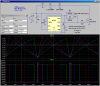
there is the circuit i will be using....except take everything away that is connected to pin 3...there will be a mosfet connected to that...

anyways...which capacitor controls the frequency?? C1 or C2? and what would be the math formula for a PWM 555 timer to determine the frequency? i was researching alot on google for the formulas but they all have to deal with astable or monostable mode only. i couldn't find anything specifically for PWM operation of a 555...any help anybody??
i was wanting to get the timer to oscillate at around 100Khz.
 
The datasheet for every 555 shows that the capacitor to ground at pin 2 and the resistors control the frequency.
I think that is a low frequency PWM circuit because if the resistances are low enough for 100kHz then the pin 7 will be shorted by the very low resistances.
 
well, i kept the resistances the same but i changed C1 to 390pF....using that formula 1.44/((R1+R2+R2)*C1).....that gave me roughly 100Khz?
 
You may want to read this link which has a similar PWM circuit using the 555. It also has a pretty good explanation of the circuit's operation. The circuit also includes a MOSFET for driving the small motor.

Ron
 
When the pot is centered then its effective value is 50k plus the diode resistances. The graph shows that the capacitor should be about 200pf for 100kHz. The diodes will require less capacitance for 100kHz.
Try it.
 
ok yah i'm definitely gonna go read those two links because i just finished doing some testing with the buck converter and the timer is definitely taking down the voltage some, but the pot is practically doing jack squat.
 
The datasheet for every 555 shows an output high voltage of 1.35V less than the positive supply voltage when it has a load current of only 1mA.
Haven't you looked at the datasheet??

You have not shown your "buck converter circuit" so we don't know what is wrong with it.
 
SMPS Basics - The Buck Converter

that first diagram is essentially what i'm using....i just want to start out simple before going into a big one....the switch is a IRF640, the Diode is a 10A 40v Schottky diode, the inductor i believe is around 500uH, the output capacitor is a 10mF 63v (can handle 4A ripple current)....the diagram doesn't show the input capacitor, but it is a 220uF 250vdc cap.

i eventually am going to run this off-line, but for testing, i'm using a variac right now so that i get 34vdc on the input capacitor....the output was only at around 20-22vdc no matter how much i turned the pot on the old circuit. I'm building the new one from Reloadron on my breadboard right now
 
Here is my suggestion. The frequency is nominally 95kHz. It varies slightly as the duty-cycle is varied. As shown, the current through the LEDs is ~100mA.
 

Attachments

  • 555pwm.png
    555pwm.png
    68.1 KB · Views: 522
Your Mosfet is N-channel but the Buck Converter circuit must use a P-channel Mosfet connected properly with something to boost the voltage from the 555 oscillator.

To get +34V from the source of an N-channel Mosfet then the gate must be +44V which is much higher than a 555 can go.
A P-channel Mosfet has the output at its drain that can easily swing up yo the positive supply voltage that is its source. But the input to its gate must swing up to the positive supply voltage for it to turn off and 34V is much too high for the output of a 555.

Why didn't you post your complete schematic??

EDIT: Too many schematics are being talked about.
 
Last edited:
why would it need to boost the voltage from the oscillator? isn't 10v enough to switch the mosfet on?.....crap, so if i want to run this circuit from mains power i'm gonna have to have gate voltage swing to the rectified mains, which is 160vdc...how in the world does that work if the gate can only handle +/- 20v?!
 
ok...i give up...what chip should i get as a controller for something like...idk, a 2 switch forward converter...i have a transformer core that i can use for that.
 
why would it need to boost the voltage from the oscillator? isn't 10v enough to switch the mosfet on?
You are using an N-channel Mosfet without a schematic. I guess its source is connected to ground and its gate is connected to the output of a 555 that has a +12V supply. When the output of the 555 goes high to +10.7V then the Mosfet turns on and its drain switches to ground.

But the switch on the Buck Converter never connects to ground. Instead it switches its positive supply voltage on and off.
A P-channel Mosfet with its source connected to +160V and a +150V and +160V gate voltage will have its drain switch the 160V positive supply on and off.
 
Status
Not open for further replies.

New Articles From Microcontroller Tips

Back
Top