Continue to Site

Welcome to our site!

Electro Tech is an online community (with over 170,000 members) who enjoy talking about and building electronic circuits, projects and gadgets. To participate you need to register. Registration is free. Click here to register now.

  • Welcome to our site! Electro Tech is an online community (with over 170,000 members) who enjoy talking about and building electronic circuits, projects and gadgets. To participate you need to register. Registration is free. Click here to register now.

How to adjust resonant frequency equals to operating frequency of circuit?

Status
Not open for further replies.

hanhan

Member
Please help me understand this section from my power amplifier textbook.
parameters-of-power-amplifier-jpg.75154

block-diagram-of-power-amplifier-jpg.75155

rf-power-amplifier-jpg.75156


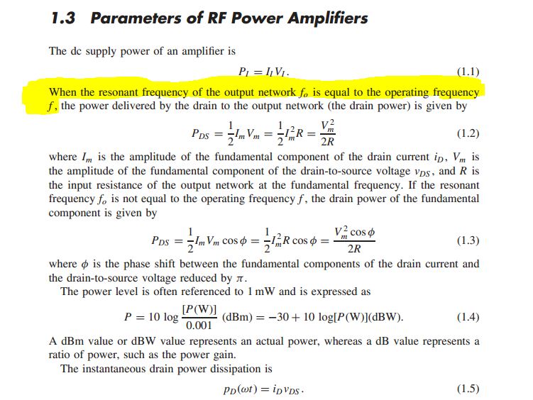
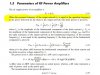
My question: We need to make the resonant frequency of the output network fo is equal to the operating frequency f and then the power delivered to load is maximum.
But the operating f frequency changes with input signal, then how can we adjust fo to get fo = f?
I think we have to have an automatic way to do that but I got stuck.
 

Attachments

  • parameters of power amplifier.JPG
    parameters of power amplifier.JPG
    90 KB · Views: 783
  • Block diagram of power amplifier.JPG
    Block diagram of power amplifier.JPG
    26 KB · Views: 899
  • RF power amplifier.JPG
    RF power amplifier.JPG
    16.2 KB · Views: 770
Hi,


This looks like an RF circuit. In an RF circuit you adjust the center frequency once to the carrier frequency and leave it. That works because most of these circuits have a much higher carrier frequency where the signal bandwidth is small compared to the carrier. So the circuit stays tuned for the carrier and works with the signal too because the Q is low enough to allow the low end and high end of the spectrum to pass. So the Q has to be low enough but that usually isnt hard to get.
 
In the power stage of the amplifier, you have to supply the output transistor with DC power. This power is supplied through L1. The impedance of L1 is 'zero' at DC but increases as the output frequency rises. By using a suitable value of inductance, the impedance of L1 can be effectively 'open circuit' to the high frequencies being amplified by the power amplifier. Any high frequency energy can then be supplied to the load 'R', and not lost in the power supply.
The network LC comprises a tuned circuit and this circuit is designed to be resonant at the frequency required. At frequencies far different to the resonant frequency, there will be a signal loss in the tuned circuit. The resonant frequency of the tuned circuit is given by f = 1/ 2*PI * sqrt(LC). The formula shows L and C can be any value so long as their product gives the correct resonant frequency. However, the frequency range over which the resonant frequency of the network is resonant can be adjusted by the choice of L versus C. This controls the Q of the circuit.
It is important to have a tuned circuit LC in the output network so that the fundamental resonant frequency is transmitted and any harmonic frequencies are attenuated by the action of the tuned circuit. The transmitter MUST only transmit the resonant freqency.
Hope this helps.
 
Thank you, MrAl and rumpfy.
MrAl,
This looks like an RF circuit.
Yes, this is a RF power amplifier.
In an RF circuit you adjust the center frequency once to the carrier frequency and leave it.
I think your "center frequency" is "resonant frequency of LC", right?
That works because most of these circuits have a much higher carrier frequency where the signal bandwidth is small compared to the carrier. So the circuit stays tuned for the carrier and works with the signal too because the Q is low enough to allow the low end and high end of the spectrum to pass. So the Q has to be low enough but that usually isnt hard to get.
Thanks, I am happy to know that. Here is a picture illustrated LC filter with various Q.
lc-filter-jpg.75161

My question now: How about if the circuit used with two different center frequency fc1 and fc2?
Is there a way to adjust resonant frequency fo from fc1 to fc2?
Or we have to manually adjust fo?
spectrum-adjustment-jpg.75162


rumpfy,
In the power stage of the amplifier, you have to supply the output transistor with DC power.
Thanks, got it.
This power is supplied through L1. The impedance of L1 is 'zero' at DC but increases as the output frequency rises. By using a suitable value of inductance, the impedance of L1 can be effectively 'open circuit' to the high frequencies being amplified by the power amplifier.
I understand what you said here but there is one thing that I am still confused. Why we need to block high frequencies (through using RF choke)?
Any high frequency energy can then be supplied to the load 'R', and not lost in the power supply.
Could you explain more? I don't know why these high frequencies relates to energy loss in power supply.
Aha, in small signal model, L1 is in parallel with R. At high frequencies, the current through L1 is zero and therefore all current is diverted to R. And no losses in RF choke, right?
The network LC comprises a tuned circuit and this circuit is designed to be resonant at the frequency required. At frequencies far different to the resonant frequency, there will be a signal loss in the tuned circuit. The resonant frequency of the tuned circuit is given by f = 1/ 2*PI * sqrt(LC). The formula shows L and C can be any value so long as their product gives the correct resonant frequency. However, the frequency range over which the resonant frequency of the network is resonant can be adjusted by the choice of L versus C. This controls the Q of the circuit.
It is important to have a tuned circuit LC in the output network so that the fundamental resonant frequency is transmitted and any harmonic frequencies are attenuated by the action of the tuned circuit. The transmitter MUST only transmit the resonant freqency.
I got it.
Hope this helps.
It really helps. Thanks.:D
 

Attachments

  • LC filter.JPG
    LC filter.JPG
    26.5 KB · Views: 769
  • spectrum adjustment.JPG
    spectrum adjustment.JPG
    20.7 KB · Views: 673
Hi,

Yes i called it the center frequency because it's the peak of the response. It's also the resonant frequency here.

In lower frequency circuits we can use switched capacitor filters which allow a lot of flexibility in the filter tuning, but for RF work i think you have to use a varactor diode (also called varicap) which allows changing the capacitance of the capacitor used in the circuit. Of course you can also use a switch to switch one in and the other out. CB radios did this to change channels by switching crystal pairs in and out.
 
Thanks,
Yes i called it the center frequency because it's the peak of the response. It's also the resonant frequency here.
That makes sense now.
In lower frequency circuits we can use switched capacitor filters which allow a lot of flexibility in the filter tuning
I didn't know about " switched capacitor filters" but I have just searched about it.
switched-capacitor-filter-jpg.75169

This is a RC filter with R changeable and the filter in my original post is LC filter.
I don't know when we need to use RC or LC filter. Please explain?
Of course you can also use a switch to switch one in and the other out. CB radios did this to change channels by switching crystal pairs in and out.
Do you mean that in this case we can use two filters with different resonant frequencies and a switch is used to choose each of them?
If so, how can we know the time to switch from the filter to the other? I mean how can we switch between two filters? We do it automatically or manually?
 

Attachments

  • switched-capacitor filter .JPG
    switched-capacitor filter .JPG
    14.3 KB · Views: 858
Hi,

In reverse order...

The radios and other devices use manual switching to switch in or out caps, filters, inductors, crystals, etc. To do it electronically you'd have to use a frequency detector i guess and maybe a relay or something.

RC filters are used when loss of power isnt a big concern because there can be a lot of loss in the R. LC filters have minimum R (parasitic) so there is minimum loss so they are better in circuits which cant put up with a large power loss.

The switched capacitor filter you have shown there is a good example of where we have to impose somewhat fictional values for the parasitics, which are very very important for that particular circuit. Note there are no resistors in series with the switches, so theoretically if we took it to be exactly as drawn we could not truly analyze it because once the first switch turned on for the first time it would cause an infinite current in the capacitor, and there is no approximation that could help. The only resort is to imagine what the parasitics might look like for both the switch and the two caps, and if possible find out the equivalent series resistance of the switches (which might give us a range of values rather than one fixed value) and go from there.
These circuits are not hard to analyze once we know that information though. But again they are limited to lower frequencies unless of course you can find a switch that operates at a very high speed, which would have to be somewhere in the region of 2 times faster than the target frequency or better if distortion was an issue. The averaged AC model for the switch is Reqiv=Rsw/D where D is the duty cycle and Rsw is the internal series resistance of the switch. The circuit can then be analyzed for frequencies lower than the switching frequency in the same was as for fixed resistors, with the exception of the noise introduced by the switch.
 
Status
Not open for further replies.

New Articles From Microcontroller Tips

Back
Top