Continue to Site

Welcome to our site!

Electro Tech is an online community (with over 170,000 members) who enjoy talking about and building electronic circuits, projects and gadgets. To participate you need to register. Registration is free. Click here to register now.

  • Welcome to our site! Electro Tech is an online community (with over 170,000 members) who enjoy talking about and building electronic circuits, projects and gadgets. To participate you need to register. Registration is free. Click here to register now.

How the self-bias technique work?

Status
Not open for further replies.

hanhan

Member
Hi,
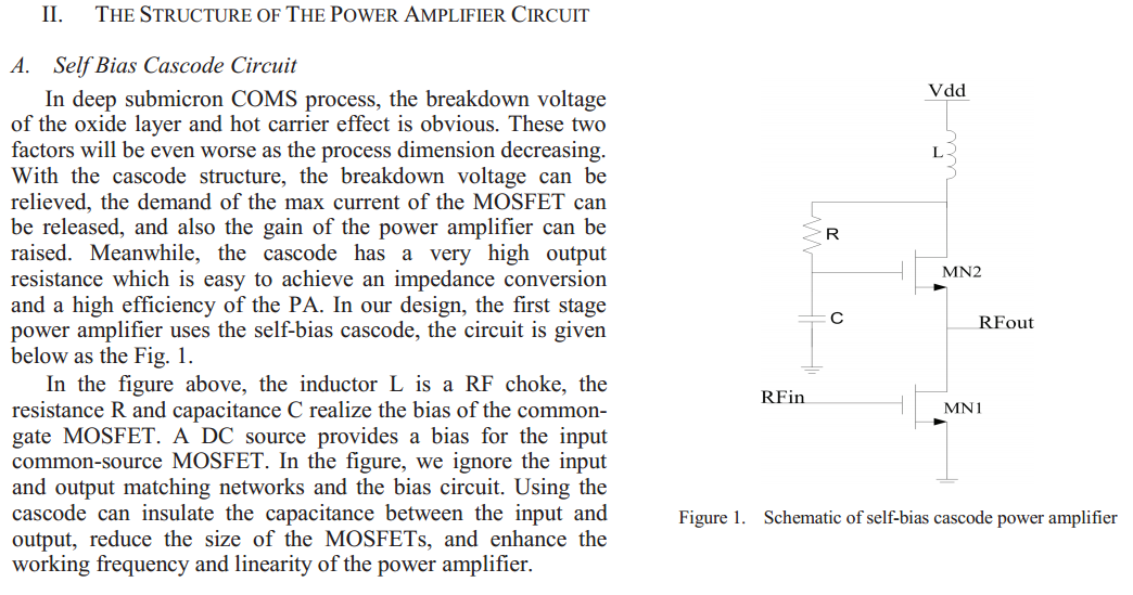
I am struggling about self-biased cascode. Here is a section that describes about self-biased cascode technique in a paper, but it is not clear to me.
( A 900MHz High Efficiency and Linearity Adaptive CMOS Power Amplifier )
Please help me understand how self-bias cascode work? Why we need the capacitor C here?

self-bias-cascode-modified-png.80836
 

Attachments

  • self-bias cascode (modified).PNG
    self-bias cascode (modified).PNG
    200.4 KB · Views: 1,308
Last edited:
MN1 operates as a common source stage, and MN2 operates as a common gate stage. The capacitor ensures that the gate of MN2 is held at RF ground; this ensures that MN2 is operating as a common gate stage.
 
I think that there is a error in the diagram. RFout should be connected to MN2 drain. Then C2 short MN2 gate to GND for AC signal. So MN2 can work as a common-gate amplifier.

Also I don't undrestend why this type of a biasing network is called "self-bias". For me only JFET and vacuum Tube can work in real "self-bias" network.
 
Thank you, The Electrician and Jony.
The Electrician,
MN1 operates as a common source stage, and MN2 operates as a common gate stage. The capacitor ensures that the gate of MN2 is held at RF ground; this ensures that MN2 is operating as a common gate stage.
That makes sense! Then at DC, C is open circuited and thus Vg = Vdd
With small signal AC, C is shorted to make it common gate, right?
If so, as my understanding, the capacitance C has to be very large at the operating frequency of the circuit. Are there any other constrains in choosing C?
Jony:
I think that there is a error in the diagram.
Sorry Jony, I think there is no error. I have seen many similar configurations
RFout should be connected to MN2 drain. Then C2 short MN2 gate to GND for AC signal. So MN2 can work as a common-gate amplifier.
If MN2 is common gate then the DC voltage at gate has to be constant, right?
Also I don't undrestend why this type of a biasing network is called "self-bias". For me only JFET and vacuum Tube can work in real "self-bias" network.
Yes, I do but the circuit looks similar to my circuit in previous thread, except the capacitor C.
https://www.electro-tech-online.com/threads/input-impedance-of-self-biased-stage.138313/
 
That makes sense! Then at DC, C is open circuited and thus Vg = Vdd
With small signal AC, C is shorted to make it common gate, right?
Yes
If so, as my understanding, the capacitance C has to be very large at the operating frequency of the circuit.
Larger??
This capacitor must provide low resistive path for the RF signal. For example Xc = 0.1ohm and F = 900MHZ we have

C > 0.16/(0.1 * 900MHz) = 1.8nF

Is that large capacitor ?

Sorry Jony, I think there is no error. I have seen many similar configurations
Very strange. So how can CS stage insulate capacitance between input and the output?
If MN2 is common gate then the DC voltage at gate has to be constant, right?
yes
Yes, I do but the circuit looks similar to my circuit in previous thread, except the capacitor C.
https://www.electro-tech-online.com/threads/input-impedance-of-self-biased-stage.138313/
This circuit also in not a self-biasing one.
 
Thanks.
Very strange. So how can CS stage insulate capacitance between input and the output?
Sorry Jony. I misread your post. I thought you meant the output of common source, RFout, have to be connected to the gate of MN2. :eek:
I think that there is a error in the diagram. RFout should be connected to MN2 drain.
Yes, you are right. The RFout should be taken at drain of MN2.
I meant it is better to use very large capacitor.
This capacitor must provide low resistive path for the RF signal. For example Xc = 0.1ohm and F = 900MHZ we have

C > 0.16/(0.1 * 900MHz) = 1.8nF
That makes sense. In this low pass filter, there is one condition for R, C:

[LATEX]f \textgreater \frac{1}{2 \pi RC} [/LATEX]
Where f is the frequency in which the circuit operates.
If this is the only condition for RC, then there are infinite pairs of R, C values that satisfy the inequality.
Are there other conditions in choosing R, C values? Which conditions would you take into account in choosing these parameters?
 
Last edited:
I don't have any real experience with RF designs so it hard for me to to say about this. Kept in mind that at that high frequency (900Mhz) PCB layout and component placement are very critical. I have only experience with relatively low frequency circuit (up to 100Mhz).
Also I want to ask you, how can you study RF circuits without basic knowledge about analogue electronics?
 
Last edited:
Thank you, Jony. I am trying to learn basic myself but my teacher assumes that we should have all basic until now and have to some project with RF..
 
Status
Not open for further replies.

Latest threads

New Articles From Microcontroller Tips

Back
Top