Continue to Site

Welcome to our site!

Electro Tech is an online community (with over 170,000 members) who enjoy talking about and building electronic circuits, projects and gadgets. To participate you need to register. Registration is free. Click here to register now.

  • Welcome to our site! Electro Tech is an online community (with over 170,000 members) who enjoy talking about and building electronic circuits, projects and gadgets. To participate you need to register. Registration is free. Click here to register now.

How audio is modulated here? cd4046

Status
Not open for further replies.

MacIntoshCZ

Active Member
Hello,
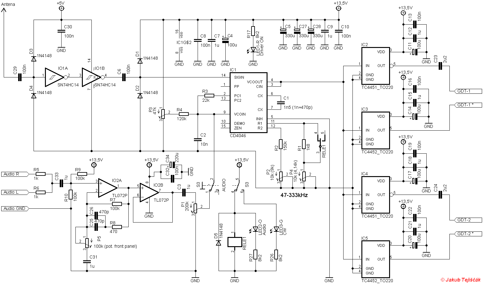
i get that cd4046 is used to lock at resonant frequency of coil but i dont understand how voltage controlled oscillator is used to modulate AUDIO to output.
Thanks for help
schema2_driver31.png
 
The 4066 is a phase lock loop IC.

The frequency of it's internal oscillator is controlled by the voltage at "VCO In" (plus the external components to set the range).
That normally tries to track the input frequency, by comparing the oscillator to the input in a phase comparator.
The output of that connects to the VCO in via a resistor.

The audio signal is also applied to VCO in while the relay is closed, which nudges the oscillator frequency up and down with the audio waveform, with the phase comparator continuously trying to match the input.

To me it does not look right; I'd expect some other components - a capacitor at least - in line with the relay. Without that, P1 is being switched in parallel with the lower half of P3, changing the DC bias as the relay opens and closes.

And turning the audio gain P1 down would effectively disable the VCO control from the phase comparator, locking it at 0V.
thanks, here is video from author of attached schematic
 
In addition to R Jenkins comments, there is something odd about that circuit.
It seems to have some particular application which is not obvious to me.

The VCO can be set to frequencies between 47 and 333kHz. Why those frequencies?
There is the ability to have the VCO generate an unmodulated carrier (CW setting) or to FM modulate it (AUDIO setting).

The 4046 implements a phase locked loop, the VCO can be locked to an external reference.
In this circuit the reference comes via two 74HC14 inverters, the input to those inverters is an "antenna".
Uh?? What? What is that antenna supposed to be receiving?

I feel that we only have half the story here.

JimB
 
Full script can be found here:
schema3_DualFullBridge11.png

schema1_zdroj11.png
 
In addition to R Jenkins comments, there is something odd about that circuit.
It seems to have some particular application which is not obvious to me.

The VCO can be set to frequencies between 47 and 333kHz. Why those frequencies?
There is the ability to have the VCO generate an unmodulated carrier (CW setting) or to FM modulate it (AUDIO setting).

The 4046 implements a phase locked loop, the VCO can be locked to an external reference.
In this circuit the reference comes via two 74HC14 inverters, the input to those inverters is an "antenna".
Uh?? What? What is that antenna supposed to be receiving?

I feel that we only have half the story here.

JimB
antenna recieve resonant frequency of coil. It helps to keep resonant frequency when you are moving with objects near coil.
 
Last edited:
I think that IC1, pin 9 should be AC coupled to P1’s cursor.
Otherwise as one adjusts the modulation index, the DC level will shift and therefore the carrier frequency.
Imagine the extreme scenario where P1 is turned all the way down to ground..... what do you think it will happen to the carrier frequency?
 
Status
Not open for further replies.

Latest threads

New Articles From Microcontroller Tips

Back
Top