Continue to Site

Welcome to our site!

Electro Tech is an online community (with over 170,000 members) who enjoy talking about and building electronic circuits, projects and gadgets. To participate you need to register. Registration is free. Click here to register now.

  • Welcome to our site! Electro Tech is an online community (with over 170,000 members) who enjoy talking about and building electronic circuits, projects and gadgets. To participate you need to register. Registration is free. Click here to register now.

Holding pressure/variable torque

Status
Not open for further replies.

Andy1845c

Active Member
Hello! It's been ages since I posted here. Glad to still see some familiar faces active!

Anyway, I am looking for something and thought maybe the automation/robotics crowd here might have some ideas.
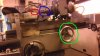
Basically what I am looking to do is power an axis on an old machine tool that has been modified to do some light production work. Currently a hand wheel moves a bed along an x axis. It its not a screw type movement like on a milling machine, but rather the bed floats on ball bearings and has very little mechanical advantage in the gearing. The hand wheel brings the bed and workpiece against a grinding stone. Currently hand pressure holds the pressure against the stone during grinding.

I want to automate this. I need some way of replacing the hand wheel with a motor of some sort that would give me the ability to hold this pressure, and vary it.

The cycle time for each piece is about 2 minutes. I don't think many (any?) electric motors would enjoy being stalled out for this long repeatedly.

I was pondering some type of hydraulic motor and relief valve, but I don't have experience with anything like that to know if its a practical solution.

A pneumatic approach would also be possible. But since I need fairly precise control, it would have to be something more than an air cylinder.

If anyone has done something like this, or seen it done commercially, I would love to hear about it.

-Andy
 
Are you talking about a surface grinder? Any of the powered table grinders I've ran have a hydraulic cylinder doing the 'X' axis movement. The X axis usually isn't able to be controlled for precise position though.
 
No, its not a surface grinder, but the bed floats just like a machinists surface grinder. The big difference is with the surface grinder you generally just make a pass all the way through, back and forth. Picture mounting something on the surface grinder bed and pushing it against a wheel it cannot pass beneath. Not that it matters per say, but basically the moving bed has a head on it much like the headstock on a lathe. This holds the part that needs to be ground. The part spins and is fed into another stone spinning the opposite direction. Holding them together for ~2 minutes creates the desired cutting edge on the part.
 
Perhaps use a stepper motor (suitably geared down) to advance a 'pusher' with a coil spring between it and the workpiece head. Sense the workpiece/stone contact. Then advance the pusher a controlled number of steps further so that the spring is compressed a known amount and hence applies a known force on the head.
 
A permanent magnet dc motor should be fine stalled with constant torque, you just need to limit the current with a constant current circuit to keep the motor heat low. As long as the stalled motor power V*I is within safe running limits you can do it continuously, just check temperature rise like with any motor setup.
 
Thanks for the replies.

A spring may be a simple solution, but I can't use a linear spring. It would have to be some sort of coil spring incorporated into the sprocket that I replace the hand wheel with. I haven't seen something like this before, but feel like something exists like that somewhere.

Mr RB - This is interesting. Would this type of motor typically be a brushed DC motor like the type you would find in a battery powered drill? I readily admit to not being a motor expert. This was one of my first thoughts, but sort of assumed the repeated stalling would be abusive to the motor and cause it to fail.
 
Can you post a pic?
They do make Flat Coil Springs;
**broken link removed**
The Question is the best way to retrofit your machine.
 
Yeah, I can take a picture later today or tomorrow
 
Depending on the amount to be ground off, this could be done with a arm mounted to the handwheel and a weight. A stop would be needed also to stop table movement. It's hard to describe in words what I mean, so if your interested in the idea I'll post a pic.

Also from doing this type of work most of my life, some thing that needs ground like this is better done with the part held adjacent to the grinding wheel instead of trying to do it with the part in line on the 'Z' axis. doing it adjacent is more accurate and less stressful on the machine and part. Can draw a pic for that too if you want.
 
The weight idea was thought of and tried. It didn't work for a few reasons. One is the part needs to be advances lightly at first into the stone. We had too much bouncing when we tried the weight. Second, I would like to semi automate this, so I would like to be able to reverse the part away from the stone as well.

Here are some pictures. Not the best, but sort of give an idea. The hand wheel I want to power is circled in green. The red circle is the grinding stone. Its a small stone mounted in a die grinder. The blue circle is the part. Actually two parts chucked up. They are curved cutting knives. They counter rotate against the stone and are sharpened.
 

Attachments

  • circles.jpg
    circles.jpg
    732.6 KB · Views: 340
  • IMAG0438.jpg
    IMAG0438.jpg
    694.4 KB · Views: 379
Those type of mounted stones really aren't made for doing something like your doing. They are too hard of a bond and also not a coarse enough grit. The bounce was probably from the spindle of the die grinder, also not made for this type work. Since you have a cutter grinder (the machine your working with) why not use that spindle and a regular grinding wheel made for the spindle? That type of wheel is a looser bond with an open grit, makes for a cooler, faster grind of your parts. Bet that with the regular grinder spindle and wheel the weight idea would work fine. I've used this trick many times over the years.
 
It's kind of a goofy situation we are working with. Picture taking a piece of 1 1/2" tube and grinding a 30 degree bevel on the inside edge, except each knife is just shy of a 180 degree arc. I can't come up with another way of doing this. Using the other spindle in the grinder would be ideal, but its not situated properly for that, even if I could find a stone that would work.

The bounce is more coming from imperfections in the stamping of the parts. They need lighter pressure at first to sort of seat into the wheel. This actually is the one problem that may make automating this challenging. Right now its all human feel to ease it in.

I've actually laid awake at night trying to come up with another way of doing this that is faster.
 
Ok that explains things, it's an inside grind, I was picturing an outside grind. Can you post a picture of what your grinding? Also have you tried feeding from the "Y" axis? Using just the front edge of the grinding wheel? I love figuring out machining puzzles, and have a outside the envelope thinking on stuff from where I served my apprentiseship. A small shop that did many involved projects with simple machines.
 
Heres the knives -
 

Attachments

  • curvies.JPG
    curvies.JPG
    25.3 KB · Views: 334
If I am following your ideas on the y axis, we would have to only do one knife at a time and would have to have a way to rock it back and forth. I have explored this idea. The other problem with this is the direction of the grind would be different and thus the finish would be different and I am not sure the customer would be ok with that.
 
Does your grinder's head have a removable wheel arbor in it? Ones I'm familiar with are a small B&S type taper with a threaded hole in the small end of the taper.

What I was meaning about the Y axis movement is to turn the work holder head to the angle needed and have the grinding wheel parallel to Y axis. Then feed in on the Y axis, using the front edge of the wheel to grind the knives. You would use the same knife holder your using now, so two at a time grinding. Just not using the full side of the wheel, so less force needed.
 
Status
Not open for further replies.

Latest threads

Back
Top