Continue to Site

Welcome to our site!

Electro Tech is an online community (with over 170,000 members) who enjoy talking about and building electronic circuits, projects and gadgets. To participate you need to register. Registration is free. Click here to register now.

  • Welcome to our site! Electro Tech is an online community (with over 170,000 members) who enjoy talking about and building electronic circuits, projects and gadgets. To participate you need to register. Registration is free. Click here to register now.

"High Voltage" Regulator

Status
Not open for further replies.

Overclocked

Member
(With Respect to 12V ofc.)

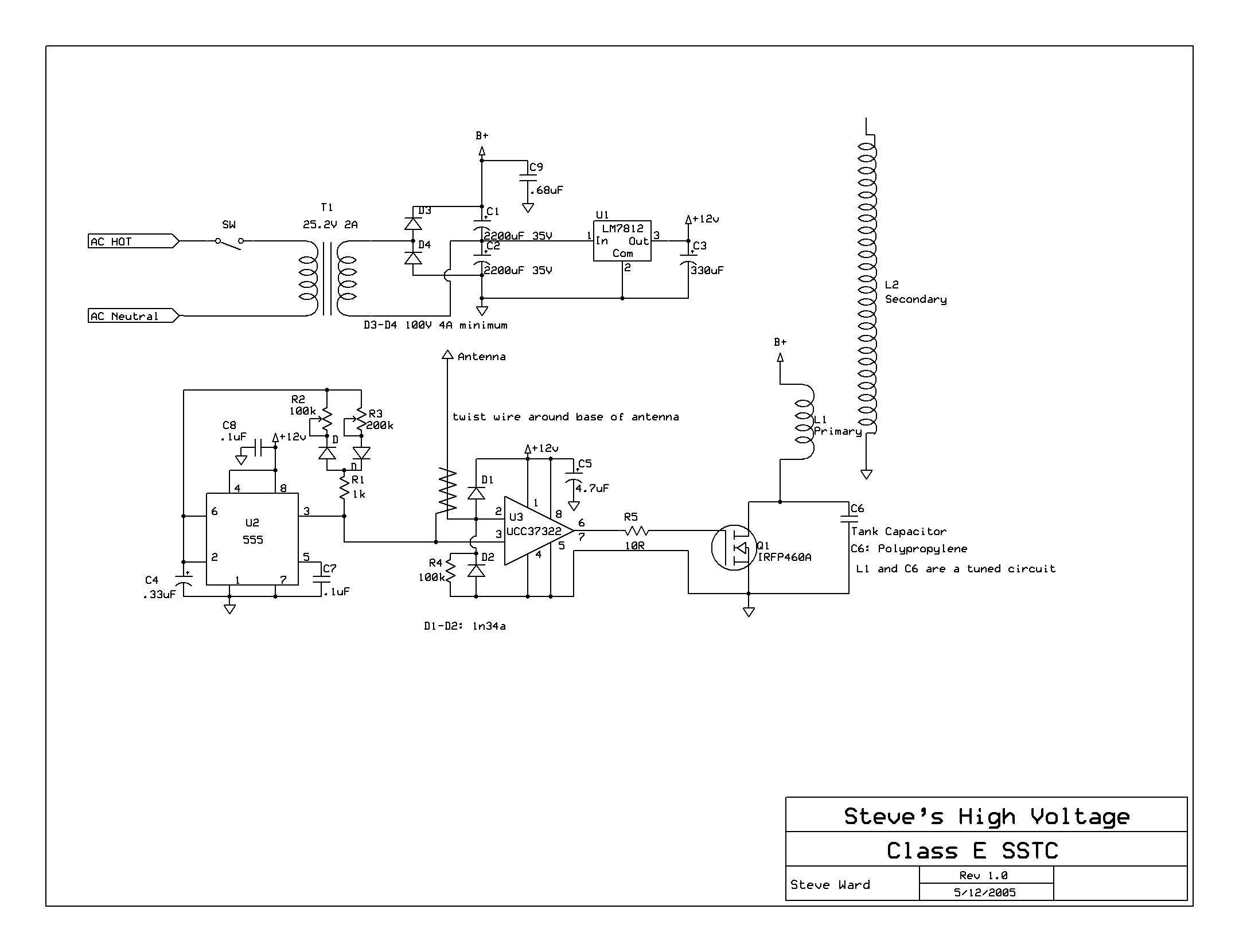
I have a project that requires a relatively high voltage, with respect to a low voltage. Its basically switching a high voltage load using a mosfet for a class E SSTC I intend to build eventually. The driver (UCC3722) uses a 12v Supply. The original circuit uses a 25VRMS transformer, but I cant find one for cheap. The transformer I have outputs 74.4VRMS / 117.36V Pk-I know it will be about 1.4V less after rectification.

I plan on using a LM317 (or LM7812) to power the 555 and the Driver. Im going out on a limb to say it probably wont need more than 1 amp, but even 1 amp is a lot. However, it can only be used for a differential voltage of up to 40V. Can I just use a Simple Series Pass Voltage regulator to lower the voltage before the LM317? (or LM7812). The only circuit I can find is this document (https://www.ti.com/lit/an/snva583/snva583.pdf). To me all it looks like is what I proposed. Nothing complex. I think I would get rid of R3, since I dont need a current limit.

Here is the original schematic of what I intend to build. I dont plan on using the voltage doubler because my Supply voltage is already what the doubled value would be. The "easy" solution would be to just use a small transformer to power the driver and 555 timer, but that would be easy. I wouldn’t learn anything that way :)

ClsESSTCsch.JPG
 
Last edited:
Regarding your schematic:
a) C1, C2 are 35V and you are putting 35V on them.
b) LM7812 has a max input of 35V. See data sheet.
c) Could not get your link to work.

See attached data sheet for a HIGH voltage regulator. Keep the current down or any linear regulator will get hot.
 

Attachments

  • TL783.pdf
    588.7 KB · Views: 336
Regarding your schematic:
a) C1, C2 are 35V and you are putting 35V on them.
b) LM7812 has a max input of 35V. See data sheet.
c) Could not get your link to work.

See attached data sheet for a HIGH voltage regulator. Keep the current down or any linear regulator will get hot.

Its not my circuit, I noticed that when I was looking over things and thought "Those should be twice 35V"

Try this link: https://www.ti.com/lit/an/snva583/snva583.pdf
 
(With Respect to 12V ofc.)

.............................................
I plan on using a LM317 (or LM7812) to power the 555 and the Driver. Im going out on a limb to say it probably wont need more than 1 amp, but even 1 amp is a lot. However, it can only be used for a differential voltage of up to 40V. Can I just use a Simple Series Pass Voltage regulator to lower the voltage before the LM317? (or LM7812). The only circuit I can find is this document (www.ti.com/lit/an/snoa648/snoa648.pdf‎). To me all it looks like is what I proposed. Nothing complex. I think I would get rid of R3, since I dont need a current limit.
.......................
The link doesn't work for me so I don't know what R3 is for.

You can use a simple series pass transistor regulator to lower the voltage for the input to the LM317. The transistor can be a NPN or an N-MOSFET transistor in a emitter/source follower output configuration with a zener diode to provide the voltage to the base/gate. The output voltage will be the zener voltage minus the base-emitter or gate-source voltage. The transistor voltage rating should be at least 25% greater than the maximum input voltage to the transistor. Note that the transistor dissipation will be equal to the maximum output current times the voltage drop (input voltage minus output voltage) across the transistor.
 
117V in, 12V out at 1A? You sure are masochistic :eek:.
The "easy" solution would be to just use a small transformer to power the driver and 555 timer, but that would be easy. I wouldn’t learn anything that way
What you will learn is that dissipating ~100W will be a challenge and expensive. Go the easy/cheap route :).
 
117V in, 12V out at 1A? You sure are masochistic :eek:.
What you will learn is that dissipating ~100W will be a challenge and expensive. Go the easy/cheap route :).
The 'easy' solution would be to power the driver from its own separate 12V source. but silicon is cheaper than copper.

Also I updated the link in the original post
 
but silicon is cheaper than copper.
Have you factored in the cost of the enormous heatsink?
 
Have you factored in the cost of the enormous heatsink?
I had a chuckle, I had forgotten about this, and after thinking about it, 120v-40 (the max a LM317 or LM7812 can handle) would leave a 80V drop across the transistor. Even at 1 Amp thats 80W, never mind what the LM317 would be dissipating itself..

I might be making things more complex than they are. I forgot that there is also a 6VRMS (9v pk) on my transformer. I may just be able to use a boost converter to get 12V. But still, the question remains, what is actually taking up 2A (if that). I doubt that the driver is using that much, and hell, I doubt that the Primary Coil is using that much as well. Infact, I doubt that the capacitor doubler can provide that much current. I also wonder why the Author didnt use a SMPS to step down the voltage. I could see that maybe noise would be a issue, but you can always follow a SMPS with a LDO.

Here is the original site:

https://www.stevehv.4hv.org/classEsstc.htm

After thought: Im looking around more on the surplus sites and I see theres a few transformers that would suit my needs for cheap enough
 
I forgot that there is also a 6VRMS (9v pk) on my transformer. I may just be able to use a boost converter to get 12V.
Or just use that capacitor doubler to do the job.
 
It looks like the whole thing only draws about 15 ma from the +12. You could probably do it with a 12 volt zener, 5K 5watt resistor and a 100 Ufd. cap
 
Status
Not open for further replies.

Latest threads

New Articles From Microcontroller Tips

Back
Top