Continue to Site

Welcome to our site!

Electro Tech is an online community (with over 170,000 members) who enjoy talking about and building electronic circuits, projects and gadgets. To participate you need to register. Registration is free. Click here to register now.

  • Welcome to our site! Electro Tech is an online community (with over 170,000 members) who enjoy talking about and building electronic circuits, projects and gadgets. To participate you need to register. Registration is free. Click here to register now.

High side switch

Status
Not open for further replies.

andy257

Member
Hi All,

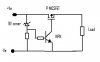
made a high side switch but it does not work quite how i want. I want a "snap" action from the switch. When the zener conducts the switch should be closed and when its not conducting open.

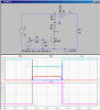
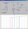
The circuit does this but its not very accurate. I am using a 9.1V zener but the switch actually works at around 9.6 to 9.7V. I want it to work as close to 9V as possible.

Can anyone suggest some improvments?

Thanks
 

Attachments

  • switch..jpg
    switch..jpg
    12.6 KB · Views: 405
The P-MOSFET is connected backwards so power will flow through the parasitic diode all the time.

There is not pull-up resistor on the gate so even if it were connected correctly it would always be on due to the leakage current through the BJT.
 
Here is how I would do it. The source and drain are interchanged in your diagram.

Note the voltage divider R2/R3 and how it controls the source to gate voltage, keeping it less than what would otherwise blow the gate.

Note how I cause the small signal NPN to switch at ~2.5V, as if it were being driven from a logic signal.
 

Attachments

  • D69.png
    D69.png
    34.1 KB · Views: 453
Last edited:
The problem with that is the base voltage of the transistor can have a very wide voltage range. This can be solved by connecting a 5.6V zener in series with the base.

I would also advise adding some hysteresis which can be solved by adding a 1M feedback resistor.
 
The problem with that is the base voltage of the transistor can have a very wide voltage range. This can be solved by connecting a 5.6V zener in series with the base.

I would also advise adding some hysteresis which can be solved by adding a 1M feedback resistor.

I missed the requirement that this be a voltage dependent switch such as would be used to disconnect a load from a battery as the battery discharges. I though that the OP just wanted a high-side switch, but I see now that he wants more.

Here is revised circuit. This one has hysteresis and snap-action. It is adjustable as shown.
 

Attachments

  • TL431Disconnect.png
    TL431Disconnect.png
    42.3 KB · Views: 437
Thanks for the replies. Yes my circuit is wrong, I drew it in a rush. I actually do have a gate source resistor in the circuit but I just never drew it. Regardless of how I've drew my circuit believe me it works. My problem is getting the thing to switch as soon as the Zener conducts. Where does the inaccuracy come from?
 
The Vbe of the NPN is ~0.65V, and it adds to the Zener voltage.
 
Ah yes, that makes sense. So I need 9v for Zener to conduct but also an aditional 0.7 for the vbe.
 
Mike - I am looking for this exact same functionality, for a 12V sealed lead acid battery in a solar-powered robotics project. I'm actually down to the wire as I need to ship this across the country on Thursday, and I need to make a couple of these. I tried designing my own with a zener and a relay but it didn't work out so well:)

What would the max continuous amperage be that I could run through this? I think my load will peak somewhere around 7A. This circuit looks great, few parts which is really good for me...

Does the Zener or any other parts have a power rating or can it all be like 1/4 W or 1/2 W? So happy to have found someone working on this exact problem. Strange it's been hard to find anything turnkey that's not huge and/or expensive...

Thanks!!
 
BTW I'm using the 12V battery to power some motors, under the control of an Arduino. I have a 5V regulator for the Arduino and the motor driver boards. I need to watch the 12V signal, but I could in fact use that signal to switch off only the 5V regulator's output. It's only a 1A regulator so that reduces the power requirement. I guess I could replace the load in your circuit with a relay or something to switch the 5V power.
 
Mike - Well I would say I tried to follow it:) yesterday but not today. It looks like you've posted the same design there, as well. I should tell you I'm a sculptor, not an engineer, but I'm force-feeding this all to my self in order to do some robotics work. Too many other issues got in the way of me sorting this one out earlier. It's a great piece though, with two different sculptural "creatures" communicating wirelessly to coordinate activities. And I'm up against the wall with a piece that ships in two days, and I need help especially in confirming that a given design - whether I have a clue how it works or not - will do the job.

In any case, I don't have time to look much further and this design looks the simplest of what I've found so far. So I'm going to see if I can round up the parts and start building these tonight.
 
If my 12V power requirement is too great for the mosfet, could this be adapted slightly so that I'm using the mosfet to switch the output of my 5V regulator (which is of course powered by the same 12V source)? Even 'though I'm only using a 1.2 AH sla battery, I'm going to be hitting it hard when the Pittman gearmotors kick in. I have current-limiting power resistors on the motor which should keep the peak currents in the 7-9 amp range, and I have .33F of carbon nanofoam caps to handle some of that... But it's probably too high a load for the mosfet, yes?
 
You can get MosFets which will switch >50A. Are you needing to switch the 12V battery High-side based on what the battery voltage is?
 
I saw a spec for an NTE2397 which says 10A, which x-refs to LM431, but they don't have it at Fry's. They do have an NTE2377 rated at 8 amps. That's probably cutting it close but it's the best I've got at the moment.
 
I saw a spec for an NTE2397 which says 10A, which x-refs to LM431, but they don't have it at Fry's. They do have an NTE2377 rated at 8 amps. That's probably cutting it close but it's the best I've got at the moment.[/QUOTE

The NTE2397 is an N-Channel FET; you need a P-Channel

The LM431/TL431 is a voltage regulator IC; not a FET
 
Dang. Could not find any IRF7204, as in the drawing, at either of the shops around or on the NTE x-reference page; only IRF720. Sorry the NTE2397 xrefs to IRF720. Not to LM431. For LM431, Fry's has NTE999. My mistake...hard dealing with this at work:)
 
Status
Not open for further replies.

New Articles From Microcontroller Tips

Back
Top