Continue to Site

Welcome to our site!

Electro Tech is an online community (with over 170,000 members) who enjoy talking about and building electronic circuits, projects and gadgets. To participate you need to register. Registration is free. Click here to register now.

  • Welcome to our site! Electro Tech is an online community (with over 170,000 members) who enjoy talking about and building electronic circuits, projects and gadgets. To participate you need to register. Registration is free. Click here to register now.

High Current MOSEFT Circuit Resistors

Status
Not open for further replies.
It just occured to me there are a bunch of different snubbers terms floating around. You can use an RC snubber in parallel with the MOSFET or the coil. Having it across the coil will reduce the speed though not as nearly as bad as a schottky diode. You can use the zener method across the MOSFET. Or you can use the schottky diode across the injector (lowest clamping voltage but also keeps the injector on for the longest as well).

I forget if zeners breakdown fast or slow. Maybe Jaguar knows, but you might require an RC snubber in that case (either across the transistor or injector) to keep things under control until the zener breaks down to save the day.

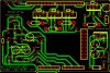
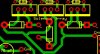
Either way it's easy to add slots for these on a PCB layout for RC snubber, zeners across the MOSFET and RC snubbers, schottkys across the injector and mount the components as needed. Just remember to monimize loop widths and trace lengths for all of them.
 
Last edited:
First, about the PCB. All of my traces are shorter than 5 inches. Would that be good? If it helps, I will post my PCB design. Let me know. I did go with a Schotty across the MOSFET. I can make it a Zener (either parallel or anti-parallel, I forget), but I really do want to keep my board as small as possible. Adding another RC snubber would take a lot of space, but it would also make keeping all traces on one side harder. By the way, what do you mean by "mnimize loop widths"? I'm not sure what you mean by loop.

Which do you think would be best for an ignition coil: an RC snubber, a Schottky, a Zener, or an RC snubber with a diode? It has a [+] and a [-] terminal, but also has a +60kV output terminal (grounded to the chassis). Also, should a Schottky be across the NMOS? I know you said
RC snubber, zeners across the MOSFET and RC snubbers, schottkys across the injector.
Does that mean that I can't have a Schottky across the NMOS?

Sorry if I don't seem to understand; this is my first experience with electrical design ever. But thanks for all the help!
 
How can you put a Schottkey diode across the MOSFET? One way its blocking and serving no useful purpose. The other way it is shorting the MOSFET out.

A 47v zener across each injector/solenoid MOSFET with the cathode toward +12v and you'll be golden. 350 volts worth of zeners in series across the ignition driver- cathodes toward +12v and you'll be fine. Forget about snubbers and Schottkeys.
 
So for some reason, I did not see the posts (on the second page)... Anyway, I decided on this NMOS (https://www.electro-tech-online.com/custompdfs/2010/11/FD2FFDPF5N50T.pdf).

Jaguarjoe, this is supposed to run a max of 4000 rpm. Think lawnmower engine. Anyway, from what I've read, with high impedance fuel injectors you don't put ballast resistors in the circuit. The coils are around 12-20 ohms. Less than 1 amp is consumed.

Dknguyen, I posted (later/earlier, I'm not sure how it will appear) a question about what configuration you think would be best (and you too Jaguarjoe). I am thinking Zener across the NMOS, after reading more about it. The Zener I am looking at is (Digi-Key - 1N5368BGOS-ND (Manufacturer - 1N5368BG)). If I use a Schottky, it would be (Digi-Key - 1N5820-E3/54GICT-ND (Manufacturer - 1N5820-E3/54)).

And thanks for letting me know about the parallel vs. series stuff. I was concerned that there would be a voltage drop like that. Just wondering, because (I think) power is conserved despite the configuration, in a series circuit, if each consumes 1 amp and 6V, then would 4 amps be rushing through the circuit? I say that because in parallel, it would be 2 amps at 12V, so 24W. I'm not sure if resistance changes, but I think it does. It should, at least if I remember correctly from linear algebra.
 
Last edited:
How can you put a Schottkey diode across the MOSFET? One way its blocking and serving no useful purpose. The other way it is shorting the MOSFET out.
You don't. I don't think I said that. I'm pretty sure I said schottky across the motor inductance or zener across the MOSFET.
 
First, about the PCB. All of my traces are shorter than 5 inches. Would that be good? If it helps, I will post my PCB design. Let me know. I did go with a Schotty across the MOSFET. I can make it a Zener (either parallel or anti-parallel, I forget), but I really do want to keep my board as small as possible. Adding another RC snubber would take a lot of space, but it would also make keeping all traces on one side harder. By the way, what do you mean by "mnimize loop widths"? I'm not sure what you mean by loop.

5" is very very long as far as snubbers, zeners, or schottkeys are concerned. You want minimum. Did I say loop width? I mean loops areas. Like the loop of circuit that is formed whenever you connect a diode or RC snubber across a inductor or MOSFET.

Which do you think would be best for an ignition coil: an RC snubber, a Schottky, a Zener, or an RC snubber with a diode? It has a [+] and a [-] terminal, but also has a +60kV output terminal (grounded to the chassis). Also, should a Schottky be across the NMOS? I know you said

Does that mean that I can't have a Schottky across the NMOS?

Sorry if I don't seem to understand; this is my first experience with electrical design ever. But thanks for all the help!

Correct it won't do anything. If you want anything across the MOSFET it has to be an RC snubber or a zener. They are doing different things. The schottky works by conducting current in it's forward direction while the zener works by breaking down and allowing current to flow "in reverse" through it. That means they need to be in different parts of the circuit to do similar jobs. RC snubbers don't have polarity so they can be used across the MOSFET or the motor inductance.

Dknguyen, I posted (later/earlier, I'm not sure how it will appear) a question about what configuration you think would be best (and you too Jaguarjoe). I am thinking Zener across the NMOS, after reading more about it. The Zener I am looking at is (Digi-Key - 1N5368BGOS-ND (Manufacturer - 1N5368BG)). If I use a Schottky, it would be (Digi-Key - 1N5820-E3/54GICT-ND (Manufacturer - 1N5820-E3/54)).
Hard to say what is best since I don't know much about injectors. I don't deem shut off time too important so I tend towards the schottky diode across the motor more than the zener across the MOSFET (obviously Jag feels differently). RC snubbers just depends on how demanding things are. They have some pretty severe disadvantages in implementation. Mainly cost and difficulty to size, and they can be large. They carry pretty heavy inefficiency (ie. heat) and cost penalites for overdesigning them and if underdesigned they might not be effective enough. It's a lot easier if you have a diode (which is comparatively dead easy to select) elsewhere to clamp the voltage to a set level and just rely on the snubber to hold the fort until the diode has time to activate.

And thanks for letting me know about the parallel vs. series stuff. I was concerned that there would be a voltage drop like that. Just wondering, because (I think) power is conserved despite the configuration, in a series circuit, if each consumes 1 amp and 6V, then would 4 amps be rushing through the circuit? I say that because in parallel, it would be 2 amps at 12V, so 24W. I'm not sure if resistance changes, but I think it does. It should, at least if I remember correctly from linear algebra.

No. Each motor sees less voltage which means less power. Furthermore, motors are not constant current sinks so lowering the voltage also decreases the current which means even doubly less power.

In parallel is easy to understand. It's like running the two motors side by side each connected to it's own battery (or connected in parallel to the same battery, of course). In series, there is less available voltage and as a result less available power to each motor. Their performance becomes linked and one motor loading down will affect the other motor.

For example, let's say each motor is meant to run off 12V and normally draws 1A. Connected in parallel, each motor draws 1A and 12V resulting in a total consumption of 12V@2A. Each motor operates independently and one motor getting more loaded and drawing more current doesn't affect the other motor (as long as the battery can support the total current draw). Simple.

In series each motor sees less than 12V because that 12V gets divided up between each motor. How much goes to each motor depends on the motor itself (whether they are the same or identical motors) as well as how much load is on each motor (whether they have the same torque load being applied or not). But the same current flows through both motors (dictated by the total impedance of both motors based on their individual loads). Their performance becomes linked. Because each motor is also basically being powered by a voltage lower than 12V they will have less output, draw less current and have a lower stall torque (stall more easily).

When a motor gets more loaded it's impedance decreases which makes it draw more current if it's connected to a constant voltage supply. This results in higher power draw to drive the heavier load. But if connected series it's not a constant voltage supply. The more heavily loaded motor with its lower impedance will see less of the supply voltage and the more lightly loaded motor with its higher impedance will see more of the battery voltage (sort of like a resistive divider). So the more heavily worked motor gets less power allocated to it and the more lightly worked motor gets more power allocated to it. It's like a car differential where if you lift one wheel off the ground it gets all the torque and spins like crazy doing nothing while the wheel still on the ground gets no torque and just sits there. It's not productive unless the load on both wheels or motors are balanced.
 
Last edited:
Ok, so I am going with a Zener across the NMOS. Should my circuit be: +12V--->[+]injector[-]--->[drain]NMOS[source]--->Gnd with a Zener connected with the cathode on the drain side and the anode on the Gnd side? Jaguarjoe said to have the cathode toward +12V, which would indicate that it should have the cathode connected to the injector [-] terminal.

For trace length, that is the absolute longest in all my circuits. Otherwise, Zener cathodes are about 3mm from the terminal. The terminal is a screw terminal to allow the wire from the injector to connect. The NMOS drains are about 12mm from the terminal. It looks like: cathode---terminal---drain
The Gnd traces from the anodes and the sources are (at max) 50mm from the terminal. The reason for this is that they all share a common ground terminal. I thought that it was equivalent to having a longer wire before it got to the terminal, so why not just have one terminal and make the trace longer. The trace then branches into 6 more. 3 go to sources and 3 go to anodes. A source/anode pair will only be separated by no more than 9mm. Just wondering, but could I make the connections like this:
terminal---cathode---drain and terminal---anode---source. This setup has the trace route through the pad for the diode anode/cathode before going to the source/drain instead of the traces from the terminals being separate. It would simplify my PCB design. See the attached. The close-ups of the solenoid array show the distinction I am asking about.
 

Attachments

  • Circuit (Full).JPG
    Circuit (Full).JPG
    124.6 KB · Views: 168
  • Circuit (Solenoid Array).JPG
    Circuit (Solenoid Array).JPG
    60.1 KB · Views: 150
  • Circuit (Solenoid Array)2.JPG
    Circuit (Solenoid Array)2.JPG
    52.6 KB · Views: 156
Ok, so I am going with a Zener across the NMOS. Should my circuit be: +12V--->[+]injector[-]--->[drain]NMOS[source]--->Gnd with a Zener connected with the cathode on the drain side and the anode on the Gnd side? Jaguarjoe said to have the cathode toward +12V, which would indicate that it should have the cathode connected to the injector [-] terminal.

Perfect!

Did you breadboard this project's circuit, or simulate it in Spice prior to doing your PCB? Once the board is made, its not easy to overcome a case of the "aw shits".
 
I haven't breadboarded it yet. I probably won't use a bread board because I hate the smell of burning plastic (in case stuff does go wrong). I plan to just wire everything up in a test arrangement. Then again, I might use one...
I also realized that your diagram shows the Zener across the injector. I have it across the NMOS, so should the cathode be toward the [-] terminal on the injector or the ground? I think it should be toward the [+] terminal, but I'm not sure. Also, how does this clamp the voltage? To make my life a little easier, could you make another diagram?

Mosaic, the circuit from MegaSquirt is basically what I have, but I don't understand the point of a BJT with a Zener across it. I guess it is to clamp both with one Zener, but I'm not sure.

Also, Jaguarjoe, how did you choose the numbers? 47V 5W Zener and 350V 5W Zeners? Why these specific numbers?
 
Mosaic, the article you posted uses a transistor as the example. A PNP is comparable to an NMOS right? So does that make the source = the emitter and the drain = the collector? Also, it says cathode to collector and anode to emitter.
 
Last edited:
Also, I will put a small snubber breakout board on top of the ignition coil and the solenoids/injectors. I realized that an RC snubber across the injector/ignition coil/solenoid must be as close as possible to the device. My concern with a snubber was simply the PCB footprint. Because I also have a Zener on each NMOS, the tolerances are greater, so adding a snubber would only help. I can compensate for time lag in the program easily enough, provided it is constant throughout all NMOS duty cycles.

Lastly, I have a small power regulator circuit with connections to ground, and 3 NMOS for the solenoids/fuel injectors, and 1 NMOS for the spark controller. Should I add traces to connect all the grounds? Should I even connect all the NMOS grounds? They all end up at the same battery terminal and I would still use a total of 3 wires to carry the current (18 AWG). I just feel like connecting the grounds is a good idea, similar to a ground plane.
 
You can put the zener diodes across the coil or across the MOSFETs. Either way will allow back EMF voltage to remain unimpeded until the zener diode's voltage is reached. Then they act like a short circuit. Putting them across the MOSFET is nice because they can be real close together. The cathode connects to the drain, or collector, the anode goes to gnd.
Zener diode voltage depends upon the voltage rating of the MOSFETs. The zener has to be lower than the MOSFET's Vds rating or a transistors Vceo rating. If you have 110v MOSFETs on the injector/solenoid circuits than you need a zener less than 100v to protect the MOSFETs. I picked 47v because I know it works. If you go higher the injector will close faster. The ignition driver must be rated for a very high voltage such as 400 to 500 volts. This lets you use a 350v zener for protection while allowing the back emf pulse to reach a high value before clipping. It is the back emf pulse that causes a spark to occur at the secondary. Once again, I picked 350 because I know it works (with the 400v MJ10012 darlington).
The Megasquirt system uses one amplified zener circuit that is shared between two "wire or'd" injectors. The PNP transistor is "off" until the back emf pulse from either inj1 or inj2 reaches the zener's 36 volts at which time it conducts causing the PNP to turn "on" sending the rest of the back emf pulse to ground. This circuit utilizes the current gain of the PNP to allow a low power zener to provide high power clipping.
 
Last edited:
Ok, so I am using 500V NMOS so I think I will use 400V of protection for the spark plug (2-200V in series) and just 200V on each of the injectors/solenoids. If I make space on my board, I'll throw 400V across of all of them because I do care about speed. I knew the rating had to be lower than the NMOS (thanks Dknguyen), but I wasn't sure about your choice of numbers until now. Let me what you think about 200V or 400V. Also, I feel like adding the snubber. What do you think? I can easily make a small board for those and use (relatively) cheap parts to hold the spike until the Zeners kick in.
 
Connecting the zener across the MOSFET is nice because they are close to each other. Electrically it doesn't matter.
What is the Rdson (on resistance) of the 500v MOSFETs? With 5 amps of current flowing through the ignition coil, you may be generating some heat ( P=I*I*R). The higher the Vds, the higher the Rdson.
You can try the snubber, it'll slow you down though. It's only rated to 62Hz. If it eats 1200v pulses, the cap has to be good for that but I can't picture a 100nf, 1200v cap being that small.
How much current are the MOSFETs rated for? High current means high gate capacitance means hefty gate drivers.
 
The MOSFETS have 1.4 ohms max at 10V and 2.5A. I'm not worried about heat though. I'm throwing heatsinks on the back of each NMOS and I'll have a 120mm fan cooling the system. I plan to build a nice enclosure for my project. It should dissipate 35W of power. I'm used to computers where I'm dealing with over 100W of thermal dissipation. Still, the heatsinks are rated for 2.5W... I'll do the math later. I'll probably just make my own heatsink for it.
The more I think about how the clamp works, the more I realize that I probably won't need a snubber. Anyway, I'm not switching higher than 62Hz anyway. The MOSFETS are 5A. Maybe I should put a resistor in front of the ignition coil to make sure it doesn't draw more than 5A. Either that or get a higher amp MOSFET.
 
Update: I found some (slightly more expensive) 500V, 11.5A, .65 Ohm MOSFETS. Sure it's twice the price, but I get a lot better performance. Less heat, more current overhead, same high voltage, nothing to lose but money.
 
The zener diode in picture #2 is not correct. As it stands, it is acting as a regular diode across the coil like you would do with a relay coil. 0.7v drop.
It should be across the MOSFET with a rating less than the Vds of that MOSFET, like maybe 40 volts or so.
You want to eat the spike but not slow down the injector (assuming this is an IC engine application).

No one has pointed it out so... the diode D1 symbol in the pictures is not a zener, that is actually the symbol for a Schottky.
 
Status
Not open for further replies.

Latest threads

New Articles From Microcontroller Tips

Back
Top