Continue to Site

Welcome to our site!

Electro Tech is an online community (with over 170,000 members) who enjoy talking about and building electronic circuits, projects and gadgets. To participate you need to register. Registration is free. Click here to register now.

  • Welcome to our site! Electro Tech is an online community (with over 170,000 members) who enjoy talking about and building electronic circuits, projects and gadgets. To participate you need to register. Registration is free. Click here to register now.

help understanding amplifier schematic

Status
Not open for further replies.
so the changes will be...

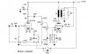
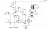
for the ECC83 one more resistor 47K before the 100K and between them a 22uF/400V decoupling capacitor.

That sounds something like.

for the EL84 a 2k2 resistor for the screen which i think it's the recomended value for the EL84... and a bigger value for the cathode probably 150ohm/4W

Go for it.

Changing the cathode resistor is essentially changing the negative bias voltage on the grid - for really high power amps you normally supply a negative bias, which will usually be adjustable, in order to get maximum power from it. For a small amp cathode biasing is beter, and it's self adjusting.

if i'm not wrong... EL84 must decipate 12W so i'm going to measure the voltage between anode-cathode and the current the tube draws so i can regulate it... is that ok or i'm still obsessed? :D
i just don't want to destroy something which it isn't as cheap and also it's not so easy to find as a simple transistor :p

The PSU voltage probably won't change a great deal, particularly with using a semiconductor bridge rectifier, and a much larger electrolytic - original valve amps would be a half wave valve rectifier, and a 16uF or so. Guitarists still like to use that configuration, as the supply sagging excessively adds to the distortion.

btw my output tube has also a blue glow... and it's very nice! :D and as far
as i know that can happen with high rush of electrons hitting things inside the tube and releasing photons.

I never like to see valves with a blue glow.
 
Don't measure the voltage from cathode to anode.
Measure the voltage from cathode to ground.
This tells you two things...in simple circuits.

Since the control grid is at ground potential (because there is no leakage from the coupling cap connected to the triode plate, and the grid resistor to ground...done very poorly in this circuit) the cathode voltage tells you the grid bias.
Cathode voltage wrt ground also tells you the current going through the tube by Ohm's law. I=E/R (cathode resistor).

That is why I asked you much earlier to tell us the cathode voltages.
 
wow!!! :eek::eek:
with just a simple capacitor...the sound changed so dramatically!

The results are very satisfying! although there's still noise which is audiable if you litteraly get your ear into the speakers cone...

nevermind! it's perfect! :D

now about the tubes...what am i going to do?? the cathode resistors are currently 2x150R/2W but EL84 is still shy... :mad:

i think i might somehow damaged them.
 
wow!!! :eek::eek:
with just a simple capacitor...the sound changed so dramatically!

It's an absolutely essential component - otherwise you're feeding mains hum straight in the amplifier.

The results are very satisfying! although there's still noise which is audiable if you litteraly get your ear into the speakers cone...

nevermind! it's perfect! :D

now about the tubes...what am i going to do?? the cathode resistors are currently 2x150R/2W but EL84 is still shy... :mad:

What do you mean by 'shy'?.
 
now about the tubes...what am i going to do?? the cathode resistors are currently 2x150R/2W.

I've just been back and looked at the original circuit, and the ones I posted.

Your original used a 135 ohm cathode resistor, I suggested increasing it - moving to 150 ohms is hardly much of an increase at all. Notice the circuits I posted, the first used 560 ohm, and the second 300 ohm.

I would suggest moving to at least 300 ohm, and see what happens then (and as suggested, measure the cathode voltage to check the current through the valve).
 
What do you mean by 'shy'?.

one of the EL84s still gets a bit red... the other one doesn't... but both
have that blue glow...


What part of "measure the voltage from cathode to ground" do you not understand?

i don't have much time now...i'll answer you later.


here's one more updated schematic of what i did (excluding the nfb which i'm about to add to the circuit maybe to day).

Nigel your schematics proved very helpful! :D
 

Attachments

  • scematic2.jpg
    scematic2.jpg
    41.7 KB · Views: 164
Last edited:
one of the EL84s still gets a bit red... the other one doesn't... but both
have that blue glow...

Well you haven't reduced the anode current worth mentioning - an obvious method based on the circuit you posted is to simply remove one of the parallel 270 ohms and half the current. Notice that's still about double the current used in the Mullard 3-3 amplifier (from the people who designed the EL84).
 
The quality of the output transformer determines how much (if any) negative feedback can be added before the amplifier oscillates.

Solid state amplifiers have a lot of negative feedback because they don't have the phase-shift problem caused by an output transformer.
 
I was interested in the screen circuit and that there was no cap there. I used Google. Lots of information here.

**broken link removed**
 
one more small update...

i also did some changes to the circuit for the nfb but i haven't yet applied it to my amp...

@flat5 you said something about a capacitor to the screen...you mean the one the datasheet shows 8uF? is it important?
 

Attachments

  • scematic2.jpg
    scematic2.jpg
    40.8 KB · Views: 248
Phase shift in the output transformer will cause the amplifier to oscillate at a high frequency and destroy your tweeter when too much negative feedback is added. The 220pF capacitor and parallel resistor have values selected to match the transformer to reduce negative feedback above a certain frequency.

EDIT: There is no negative feedback with the feedback parts feeding a huge capacitor to ground.
 
Last edited:
I don't know what data sheet you are refering to.
On the EL84 pin9 you could try an electrolytic cap to ground.
See if the hum is even less. I don't know what value. Use what you
have for now or try an 8uf. Just make sure it's voltage rating is high enough.
Much higher than the max power supply voltage before the tubes heat up. (450 vdc?)
 
EDIT: There is no negative feedback with the feedback parts feeding a huge capacitor to ground.

you mean the 10uF/25V ? i thought it would be better like this...
the previous design is more correct?


I don't know what data sheet you are refering to.
On the EL84 pin9 you could try an electrolytic cap to ground.

that datasheet, the mullard one... :p

https://www.electro-tech-online.com/custompdfs/2008/12/el84.pdf

btw what does it mean "working the output tube as triode or as pentode" ?
what's the difference? what are we trying to do by that??

[Edit]

@Audioguru i have 1/2 of the ECC83 currently spare! i could try to fix the phase shifting and see how the amp sounds... don't you think?
 
Last edited:
btw what does it mean "working the output tube as triode or as pentode" ?
what's the difference? what are we trying to do by that??

Like it says, running it as either a pentode (actually more like a tetrode) or a triode, by strapping G2 to the anode.

[Edit]

@Audioguru i have 1/2 of the ECC83 currently spare! i could try to fix the phase shifting and see how the amp sounds... don't you think?

No, it's not a fixed degree of phase shift, it will vary with frequency - basically due to the transformer. It's NOT an opamp, you can't just add feedback as you like - check the earlier designs I posted.
 
If you have a suitable electrolytic lying around try it and see if bypassing the screen lowers noise.
Still would like to know the cathode voltage.
 
Status
Not open for further replies.

Latest threads

Back
Top