Electro Tech is an online community (with over 170,000 members) who enjoy talking about and building electronic circuits, projects and gadgets. To participate you need to register. Registration is free. Click here to register now.
Welcome to our site! Electro Tech is an online community (with over 170,000 members) who enjoy talking about and building electronic circuits, projects and gadgets. To participate you need to register. Registration is free. Click here to register now.
i tried it with a Mp3 player and i can hear a huge hum with a
faint music in the background... why always must be a problem some where?
after some inspections everything "looks" fine with the circuit...after all music goes to the speakers but i don't know why it's so faint and the noise so loud.
with the Mp3 disconnected the hum still exists.
i took a piece of metal and i isolated the tubes from the transformers...
the problem wasn't there!
i noticed that if i pull the cable from the mains...the noise goes away and the music still plays for 4-5 seconds!
The hum is 60 Hz or 120 Hz from the Power Supply.
Try to decide which. If 60 it may be filament voltage leaking to cathode or ??
Do you have access to a good tube tester. Do you have a 'scope?
If you have a 'scope look for hum on the cathode of the first tube.
If the hum is 120 hz it is on the V+ line. Since the diodes are new it should be a bad electrolytic cap.
Hmm...make sure all ground connections are good.
Hmm #2...since the music is playing so soft you may have an input wiring error or again a bad first tube or coupling problem.
What is the cathode voltage on the output tube?
Is it tube drawing too much current?
flat5 thank you very much...
i think now i need your help more than ever! last time the problem with the power supply was trivial and i should have seen it....but what about now?
tube tester is not available... oscilloscope is not available...
the electrolytics are brand new nippon chemicon 150uF/400V
The mains is 230V/50Hz and looks to me the hum is in that frequency though i can't be sure on that.
i tried with other tubes but the music is still faint.
for the cathode voltage you asked..etc. i need to check it again..but i think
it's 270V
"the electrolytics are brand new nippon chemicon 150uF/400V"
They were before the transformer was connected improperly
I think they were not getting any voltage before but am not 100% sure they did not see any reversed voltage or AC. Meaning one or more might be bad. We do need to clearly see how you wired everything, esp. the power supply.
"but i think it's 270V"
Cathode voltage, not plate.
i found a mistake... i had connected the 1M resistor before the capacitor...
i also managed to fix a bit the voltages of the triodes
ECC83
#1 triode 220V
#2 triode 160V
EL84 240V
now it plays loud! although the noise still exists and i think it wont go away
until i fix the wires.
@Audioguru you're right... from a point and after the distortion is unbelievable! but the amp plays very loud for only 5-6W
the sound quality is acceptable if the volume is not too high. I think it's fine for guitar
alot of BZZZZZZZZZZZZZZZZZ! it's not the transformers... it's not the circuit! i also fixed the voltages on both the triodes
ECC83 160V
EL84 240V
also when the input is not connected anywhere... the hum is huge!!!
i'm using 1,5M resistor for the input... i don't know if that could be the problem.
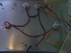
You have great long wires connected to the right hand valve base, routed right next to the heater wires - wires need to be as short as possible and away from heater connections.
The higher the input impedance, the more chance of hum pickup - for a start short the input socket out and see if it's internal or coming in the socket.
ok i did shorted the input... and wow..... it's like MEGA BASS!
the hum just changed frequency.
nigel i also want to lower the voltage on the El84 a bit... but i don't want to experiment
anymore with the voltages because last time i almost made them work at 290V!! and i don't
know if the could get burned... could you pls tell me a value for the two 270ohm resistors
so i can lower the EL84!
The first hum is 100Hz from the full-wave rectifier. Maybe the filter capacitor is not good.
The second hum (buzz) is 50Hz and is picked up from the mains or from the filament wiring.
i'm spending too many hours on this amp.. and i'm feeling i am no where!
the voltages somehow they're drifting and i haven't even touched the resistors! the ECC83 readings are 160V and 135V now...
The first hum is 100Hz from the full-wave rectifier. Maybe the filter capacitor is not good.
The second hum (buzz) is 50Hz and is picked up from the mains or from the filament wiring.
If you're using the original circuit you posted, then (like we told you) it's rubbish.
Add the decoupling components as shown in the two diagrams I posted, R5, R6, C1A and C1B in the second of the diagrams - without them you're just feeding hum from the PSU directly to the grids of the valves.
If you're using the original circuit you posted, then (like we told you) it's rubbish.
Add the decoupling components as shown in the two diagrams I posted, R5, R6, C1A and C1B in the second of the diagrams - without them you're just feeding hum from the PSU directly to the grids of the valves.
ok i'll add two capacitors... i hope it gets better with them.
i also tried two 1K resistors as voltage divider connected to the ground
and did nothing!!!!!!!!!!!!!
when i'm shorting the input the noise is not so loud and looks like it is
in lower frequency than when it's not shorted.
now about the drifting of the voltage on the ECC83.. yesterday both where regulated at 160V, today the one half of the ECC83 is 135V and the other is 160V i discovered that everytime i disconnect the input i measure ~250V on the one half of the ECC83 while the other remains steady and if i connect the source again then the voltage returns back to 160V
i want to ask... is there any chance the tube got damaged? how do i know
if the tubes are ok or not?
This site uses cookies to help personalise content, tailor your experience and to keep you logged in if you register.
By continuing to use this site, you are consenting to our use of cookies.