Electro Tech is an online community (with over 170,000 members) who enjoy talking about and building electronic circuits, projects and gadgets. To participate you need to register. Registration is free. Click here to register now.
Welcome to our site! Electro Tech is an online community (with over 170,000 members) who enjoy talking about and building electronic circuits, projects and gadgets. To participate you need to register. Registration is free. Click here to register now.
2W resisitors are overkill. Just use 1/8W resistors. You can get them from Digikey or Radio Shack. Also, use the NE555, unless you're really, really concerned about power consumption.
The resistors are probably just missing from online, I haven't clue why that should be.
I chose the TS555 because of it's lower minimum Vcc (2v) **broken link removed** than the NE555 (5v) on the datasheets I looked at. **broken link removed**
The supply is only 3.7v from a Li Ion battery at full charge, so I figured the lower power version was a safer bet.
Anything that increases battery life isn't a bad thing, although I expect I'm paying the price in terms of robustness somewhere down the line for what is probably a minimal decrease in consumption, I hope the TS555 is not too unstable!!
Since power consumption is a great concern, you might think about redesinging the transistor inverter. You might change the base resistor to 3.3K Ohms, and the collector resistor to 1K Ohm. That would change the operating current from 33 mA to 3.3 mA. Of course, the operation of that transistor is intermittent, so it might not be such a big deal. It also depends on the input requirement of your camera. My first selection of resistors was intended to make sure you had lots of margin for drive strength, and I wasn't even considering power consumption issues.
The timer only effects the motion signal, the working supply for the camera is separate. I'd imagine as long as the DVR can see roughly 3volts or zero volts it will be happy regardless of current, (within reason it's bound to need some current flowing)
So yes, lets give the lower ampage a try, I can always change it.
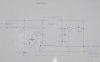
Here's the latest drawing with the updated resistors and diode removed..
and the latest parts list..
Resistors: 39KΩ, 3.3KΩ, 1KΩ Potentiometer: Hor Encl Preset 5M N46BR £0.34 **broken link removed** Capacitor: Minelect 47µF 16V VH11M £0.12 **broken link removed** Timer: TS555/6CN Low Power Timer RA76H £0.75 **broken link removed** Timer Socket: DIL Socket 8-Pin BL17T £0.20 **broken link removed** Transistor: 2N3904 QR40T £0.21 **broken link removed** 2.5MM JACK SOCKET: 4Pole - MJ-068H £1.43 per 2 2.5MM JACK SOCKET, 4P - MJ-068H 2.5MM JACK PLUG: 4Pole, METAL - PSG02797 - PRO SIGNAL £0.77 2.5MM JACK PLUG, 4P, METAL - PSG02797 - PRO SIGNAL PCB: Enclosure:
Very strange, absolutely no change in the performance at all!!!
I figured it would either work or not work, but to have not changed anything is weird!!
So I guess that would indicate no resistance between Terminal 2 on the T555 and the output signal on the collector side of the NPN.
The potentiometer is set to 1.1MΩ which should give somewhere in the 60second delay if it were working I think, but it's still under 1 second. Adjusting the pot makes no difference to the delay either way.
I will totally recheck the circuit connections later today, but can anyone see a reason for this not working based on the circuit diagram?
Your variable resistor is connected incorrectly. The wiper need to be connected ( the part with the arrow, which you show is not connected.) Connect the wiper to the 39K Ohm resistor. Sorry I missed that detail before.
EDIT: Double check the connections for the timing components, the variable resistor, 39K resistor, the 47uf capacitor, make sure of the value and orientation of the capacitor. With the variable resistor connected as drawn, you should have observed a maximum time delay. You're reporting a minimum one, which indicates to me you have a problem besides the variable resistor. Make sure you know the pinout of all your components.
My bad, I got a connection switched. Thanks for the response though, I did check everything as you suggested.
So I'm pleased to report the timer is working and is adjustable as we expected, so thanks for that.
There is something not quite right with operation though.
When the camera signals movement the recording commences a timed recording session initially, but if it doesn't see movement in the timed period, it ends recording as soon as movement stops.
eg If the timer is set for 3 seconds (Rec = record on) this is how it currently performs..
Motion, Rec 3 secs, Stop recording
which is OK, but with additional motion
Motion, Rec 3 secs, If withiin that 3 secs Motion keep recording but stop recording without timed delay should motion stop.
but it should be with additional motion
Motion, Rec 3 secs,
If withiin that 3 secs Motion, Then continue Rec 3 secs,
Else Stop
I guess the circuit needs to somehow monitor the input signal for motion and retrigger the timer.
Any suggestions welcomed. At least I now know the basic timer circuit works with the DVR and camera.. thanks very very much for that.
If I understand you correctly, the timer is working properly. If set for 3 seconds, then it will output for 3 seconds. I thought that's what you wanted.
EDIT: if, for example, the timer is set for 3 seconds, and motion is detected after it times out, then it should trigger again for another 3 seconds. You would ned a pretty major redesign to get different behavior.
One possible solution to your problem would be to build an identical timer, but connect the collector of the transistor to the "+" lead of the capacitor on the first timer. Use an R*C value that gives you somewhere from 250mS to a second or so. Feed the input from the same source as the orignial timer is fed. When you get a pulse, the second timer will discharge the first timer's capacitor, and the time process will thus be reset. You can use a 556, which is two 555 timers in a single package. If you decide to build this circuit, or a similar one, save your orignial circuit, don't just add to it. That way, you have a working circuit to reference if something goes wrong with the second one.
Hi BrownOut, I only want it to stop recording if it doesn't see motion for a timed period. (eg. 3 seconds) after it gets it's first trigger I should add.
It's doing that on the first hit of motion, but not thereafter without stopping recording and starting again. It would be better if it continued recording and only stop if it doesn't see motion for the timed period (rather than zero seconds after the initial timed period).
I hope it isn't too radical a change as the basics seem to be working great. At least some of the practical issues have been tested, which I'm quite pleased about.
I can post video of it's behaviour if that helps clarify the issues.
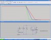
EDIT: if your signal from the motion detector is 100 mS or so, you could get away with just the transistor. In the attached diagram, the 47uf capacitor represents the same as in your original circuit. The waveform shows how the capacitor discharges for base resistances of 1k 2k and 3k. The cap can be completely discharged ( ie the timer is reset ) for a pulse of less than 100mS if the base resistor is 1k.
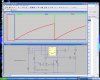
The circuit posted above passed simulation, but it has a glaring issue. Q2 is on almost constantly, consuming power, and I remember you were concerned about power. This circut operated identically, and much more efficeintly. In the simulation, a short pulse comes in from the motion detector at 100 mS and 600 mS. This input is modeled by V1, and shown in green on the wave viewer. The signal that determines the timeout of the timer is shown in red, and completely resets at each occurance of the input signal. The output in blue, remains active over the simulation period. Without the retrig circuit, the output would have gone high somewhere around 800mS.
The input from the motion detector needs to be active for somewhere around 1mS to reset the timer. That should not be a problem, as motion tends to be much slower.
LOL I didn't get a notification that you'd sent all those replies.. thanks BrownOut.
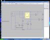
Here's 3 ready made diagrams, I was just going to ask which circuit looked best before I went ahead... looks like all the action is on Pin3 of the first timer..
Diagram from here... **broken link removed**
I'll return for a good ponder of your posts a little later
The input from the motion detector needs to be active for somewhere around 1mS to reset the timer. That should not be a problem, as motion tends to be much slower.
Hi, yes replace R2 in my circuit with the adjustable resistor and fixed one you have in your orignal circuit. Basically, everythihg will be the same as before, just add the two transistors and two additions resistors.
This site uses cookies to help personalise content, tailor your experience and to keep you logged in if you register.
By continuing to use this site, you are consenting to our use of cookies.

")