Continue to Site

Welcome to our site!

Electro Tech is an online community (with over 170,000 members) who enjoy talking about and building electronic circuits, projects and gadgets. To participate you need to register. Registration is free. Click here to register now.

  • Welcome to our site! Electro Tech is an online community (with over 170,000 members) who enjoy talking about and building electronic circuits, projects and gadgets. To participate you need to register. Registration is free. Click here to register now.

Help identifying odd looking fuse

Status
Not open for further replies.

DeLorean

New Member
Hi :D

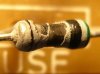
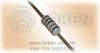
I'm desperately trying to identify this fuse.

I've spent hours trawling the internet, but I'm still none the wiser :confused:

It looks like a resistor in shape and dimensions.

I've found a few sites documenting the coloured bands on these type of fuses, but none seem work for the bands on mine :(

I've included a photo of the fuse from another identicle board I have.

Unfortunately a faulty MCR100-8 Triode Thyristor caused it to blow.

I’ve fixed the damaged components and the circuit is now working, but for the life of me can’t identify this fuse.

Any help would be greatly appreciated as it's driving me mad :(

Many thanks :)
 

Attachments

  • Image1.jpg
    Image1.jpg
    307.9 KB · Views: 3,448
It's a 500mΩ fusable resistor.
 
Many thanks to Hero999 & gerty for their suggestions :D

I've looked into Hero999 500mΩ fusible resistor, but they are not easily obtainable by the hobbyist :(

It does look similar to a Picofuse, but when it blew it did it big style (see attached photo - it splattered itself over the PCB and made me jump!).
Also the colour bands do give the impression of a fusible resistor more than a Picofuse.

The fuse in the mains socket is a 3amp, so I would have thought this would be a higer rated device as the PCB housing is not easily opened to replace anything blown.

I've only really got Maplins & eBay for spares and I don't want to compromise on safety.

There seems to be additional holes on the PCB for fuse holder clips (20mm apart).

Perhaps they changed their minds after manufacturing the PCB and went for an alternative (more resilient) form of circuit protection.

Would it be acceptable to fit PCB mounted fuse holder and fit a 20mm 3.15amp quickblow fuse or similar?

Many thanks
 

Attachments

  • Image1.jpg
    Image1.jpg
    57.5 KB · Views: 1,088
Last edited:
It's probably a normal resistor being used as a fuse.

500mΩ is an odd value, I would've expected to be something like 470mΩ.

Assuming it's a 500mΩ the rupture current will depend on the power rating but how do you know what that is?

If it's a 0.25W resistor the current which will cause the maximum power dissipation is:
I = √(W/R) = √(0.25/.5) = 707mA

That doesn't mean it will fuse when 250mW is being dissipated, it could be over 500mW and it will take some time.

It's just a gues but I'd opt for a 1A slow blow fuse assuming the resistor will blow at 500mW which would be 1A.
 
Many thanks Hero999 for all your assistance.

My quest continues :D

I've found some more additional information from another fusible resistor manufacturers:

RNF Fusible Metal Film Resistor (Sannohm)
• SUPERIOR QUALITY FUSIBLE RESISTORS WHICH ARE FLAMEPROOF DURING OPERATION
• RESISTORS FUSE IN LESS THAN 30 SECONDS AT 16 TIMES RATED POWER
• RESISTORS ARE MARKED WITH 4 COLOUR BAND CODE INDICATING THE VALUE AND A 5TH BLACK BAND DENOTING A FUSIBLE RESISTOR

Normally fusible fuses have the fifth band white, but according to this some have a black fifth band demoting it's a fusible resistor.

I've also noticed that most (if not all) fusible resistors have a matt finish and not a gloss finish.

I haven’t yet found out why the second black band (next to green) is thicker than the others?

How do you get to the value 500mΩ from the bands green, black, silver, gold?
Is there a different chart for calculating fusible resistors?
 

Attachments

  • FR.jpg
    FR.jpg
    7.4 KB · Views: 1,112
Many thanks Hero999 for all your assistance.

My quest continues :D

I've found some more additional information from another fusible resistor manufacturers:

RNF Fusible Metal Film Resistor (Sannohm)
• SUPERIOR QUALITY FUSIBLE RESISTORS WHICH ARE FLAMEPROOF DURING OPERATION
• RESISTORS FUSE IN LESS THAN 30 SECONDS AT 16 TIMES RATED POWER
• RESISTORS ARE MARKED WITH 4 COLOUR BAND CODE INDICATING THE VALUE AND A 5TH BLACK BAND DENOTING A FUSIBLE RESISTOR

Normally fusible fuses have the fifth band white, but according to this some have a black fifth band demoting it's a fusible resistor.

I've also noticed that most (if not all) fusible resistors have a matt finish and not a gloss finish.

I haven’t yet found out why the second black band (next to green) is thicker than the others?

How do you get to the value 500mΩ from the bands green, black, silver, gold?
Is there a different chart for calculating fusible resistors?

Hi,
Look at this link.
**broken link removed**

Gn/Bk/Silver
50 * .01 = 0.5R [500milliohm]
 
Last edited:
I used:

https://www.el34world.com/charts/resistor/5BandResisitor.htm

Green - Black - Silver - Gold - Black*

*=I'm assuming the last black band indicates it's a fuseable resistor.

It comes out at 4.8 ohms :confused:

This is really frustrating :(

hi,
Step back a little, basically its a 'resistor' and acts as such unless the current exceeds the rated value and it effectively burns out.

So the colour codes for normal resistors apply.

There is is no band to say its fusible, the printing on the pcb identifies it as a fusible resistor.

Green = 5 Black = so thats 50 , the multiplier is Siver which is 0.01 so 50 * 0.01 = 500mΩ

Does this help.?:)
 
Ahh thanks ericgibbs :D

Its a fuseable resistor of 0.5 ohms (+- 5%)

Sometimes I'm so thick :D

From it's size it looks like it's power rating may be 0.75W.

It's says on a label in the box that the rating of the unit is 230v~240v AC, 88watts approximately.

Only problem now is where am I going to find a 0.75W 500mΩ fusible resistor????

Just out of interest, does the thickness of the first black band mean anything?
Also what does the final thin black band denote?

I'm just curious :D

Many thanks to everyone for all your help.

It's really appreciated :D
 
Last edited:
Thanks again ericgibbs :D

I contacted a manufacturer of fusible resistors in China called Token Electronics (www.tokenchina.com).

They identified it as a:

1/2 watt
300 volt
0R5 ohm
(FRN) metal/carbon film
Fusible resistor

I've tried all the usual places e.g. Maplins, RS and Farnell (plus combing the internet), but none stock a 500mΩ device :(

Trust me to need such an illusive component :rolleyes:

Any one else have idea where I could get some?

Thanks
 
As it would seem that I will never find my "rare" fusible resistor, I think I may have found an alternative option :D

www.maplin.co.uk do a 20mm glass time delay fuse.

Part number: GL56L
500ma fuse Rated at 250Vac with a breaking capacity is 35A or 10x rated current, whichever is greater.

Comparing it with my fusible resistor (FRN-1/2W-0R5-J-T52) at:
http://www.tokenchina.com/resistor/fusible-resistor.htm

This should do the trick :D

Looking at the power wattage & fusing time:
10x for the time delay fuse and 16x~32x for the fusible resistor, it should give a better level of protection.
 
I also heard about "flameproof resistors". The look a lot like your 0.51 ohmer and they blow without burning. A blown flameproof can be identified by its discoloration in the middle portion of the resistor body.
 
Status
Not open for further replies.

Latest threads

New Articles From Microcontroller Tips

Back
Top