Continue to Site

Welcome to our site!

Electro Tech is an online community (with over 170,000 members) who enjoy talking about and building electronic circuits, projects and gadgets. To participate you need to register. Registration is free. Click here to register now.

  • Welcome to our site! Electro Tech is an online community (with over 170,000 members) who enjoy talking about and building electronic circuits, projects and gadgets. To participate you need to register. Registration is free. Click here to register now.

(Help) 60 seconds counter using 74192 & 7447

Status
Not open for further replies.

mhention

New Member
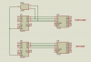
We have this project which is to make a 00-60 seconds counter using 74192 and 7447 IC. I just made a 00-99 counter with the use of the IC mentioned above and i just thought that maybe there is a way to limit the counter up to 60 seconds but i dont know how. Please help me about this guys.
 
If you want 60 count, i.e. 00-59, resetting on 60 back to 00, then you can connect an AND gate from the appropriate bits (2nd bit and 3rd bit) of the tens display to the CLR input of the counter.
 
or You can a 4017 for resetting the counter after 59 sec like this : take the carry out from the first digit feed it to clock of 4017,74192 and connect the Q6 (of 4017) to CLR (2nd 74192's) and RST (of 4017). that will do the job i think.....
 
Last edited:
Do you mean substituting the 7447 IC with 4017?
No, the 4017 he mentioned is an additional counter running in parallel with the 74192. The 7447 is not a counter; it is a 7-segment display driver.

The AND gate method I mentioned above could be implemented with two diodes and a resistor if required.
 
If im going to add an AND gate, what value of diodes and resistor do i need and where particular do i need to connect, to the output of AND gate? Sorry for the newbie questions, coz i am just starting to study Logic Circuits.
 
try something like this..

Allen
 

Attachments

  • 74192_60 PULSES.PNG
    74192_60 PULSES.PNG
    27.9 KB · Views: 6,077
If im going to add an AND gate, what value of diodes and resistor do i need and where particular do i need to connect, to the output of AND gate? Sorry for the newbie questions, coz i am just starting to study Logic Circuits.

You either use an AND gate or you can use the diode equivalent AND gate; you don't need both.

The resistor can probably be 4k7, and the diodes can probably be 1N4148, or basically any standard silicon PN junction or schottky diodes. I don't think it's very important. The cathode of each diode connects to the 2nd and 3nd outputs of the tens counter. The anodes both connect to the reset input of the counter, the resistor connects from this input to the supply voltage.
 
Status
Not open for further replies.

Latest threads

New Articles From Microcontroller Tips

Back
Top