Continue to Site

Welcome to our site!

Electro Tech is an online community (with over 170,000 members) who enjoy talking about and building electronic circuits, projects and gadgets. To participate you need to register. Registration is free. Click here to register now.

  • Welcome to our site! Electro Tech is an online community (with over 170,000 members) who enjoy talking about and building electronic circuits, projects and gadgets. To participate you need to register. Registration is free. Click here to register now.

hearing aids revisited

Status
Not open for further replies.

MrDEB

Well-Known Member
still contemplating building a hearing aid for when I go to the gym or other environments that I will sweat a-lot. Sweat plays havock on hearing aid electronics. The mics and all other electronics to be mounted on the chest using a necklace harness or ?. Have a switch for front and back mics or front only.
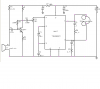
Found this little circuit using a TDA2822M stero amp (used a-lot in walkmans etc)
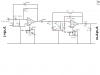
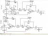
then found a speech filter circuit using a TL072.
Plan is to use two 8 ohm earphones instead of the 32 ohm headphones. Use some SMD mics
SMD Microphone (Pkg of 2)-The Electronic Goldmine
then the earphones
Replacement Earphone-The Electronic Goldmine
thinking that since the amp is stereo and found a circuit using the RDA2822 with two speakers (reconfigure the hearing aid circuit for stereo?)
BUT the TL072 shows 15v duel supply where the amp is 3v single supply. how to combine or will the TL072 run at lower voltage. Couldn't make heads or tails of data sheet Vcc
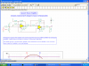
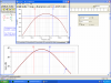
any suggestions. plan to run sim in TINA to see just how well the filter works.
 

Attachments

  • hearing aid 1..PNG
    hearing aid 1..PNG
    27 KB · Views: 694
  • hearing aid 2..PNG
    hearing aid 2..PNG
    29.6 KB · Views: 524
hearing aid filter simulation

not sure of what I am looking at but the schematic I first posted has more db gain but is this desired?
the attached screen shot shows both waves forms of both circuits
the wave form in the smaller box is my first post. the larger box shows the wave form of the circuit in this post. about 35db but a narrower wave?not as wide as the smaller box.
the second circuit shows a 5v single supply
which circuit in your opnion is better for a hearing aid filter?
 

Attachments

  • hearing circuit..PNG
    hearing circuit..PNG
    71.8 KB · Views: 532
  • hearing sinewave&#1.PNG
    hearing sinewave&#1.PNG
    91.2 KB · Views: 408
The minimum total supply for a TL072 is 7V. It works well from one 9V battery but your filter circuit is designed for a dual polarity supply.

Why use a "speech filter" that cuts all important high frequency speech consonants that reach up to 14kHz and higher? It cuts all the natural sounding low frequencies too. Don't most hearing-impaired people need equalization (boosted high frequencies, not cut high frequencies)?

I think the "replacement earphone" is garbage and won't be loud enough for a person with normal sensitive hearing. It is so cheap that it will be resonant and distorted and will mess up sounds.
 
I think you need to characterize the hearing response of your ear first. Design amp based on individual hearing. For me, I have a mid dip of around 50 dB in my right ear as tested by an audiologist. So a midband amp would work for me, I am being fitted for a custom piece as we speak.

You might be able to get a baseline response graph using an online hearing exam depending on your soundcard and headphone quality. Equal loudness contours and audiometry - Test your own hearing
 
The new speech filter uses a OPA4347 and single supply. I am just getting started as I renewed my interest when I stumbled across the amp circuit.
The earphones are just a thought as they don't look so ominius as compared to a set of headphones.
My plan is to build/expermint with a stereo hearing aid that the mics are mounted on a "vest' so mics are in front and back and all the electronics are away from sweat behind the ear..
Be really swift to design a PIC circuit that has several different bandpass filters an automatic volume control.
Somewhere on this form someone posted about building a PIC vu meter.
Will try out the hearing test. Probaly get a graph from my audiologist as my hearing aids need servicing anyway.
 
revised speech filter using OPA4347

the revised speech filter uses a OPA4347 (4 op amps in one pkg)
Single supply, 2.3-5.5v Vcc
thinking of getting one circuit built then add filters for different frequencies maybe.
Just after an experimentation type hearing device that works better than the cheapo sonic ear as advertised on TV.
Only plan on using for harsh environments like going to the gym and sweating. Hard on electronics.
Saw a circuit that automatically cuts the loud noises but need to relocate.
 
forgot attachement!!

oups
Forgot to attach revised schematic.
 

Attachments

  • hearing aid 3..PNG
    hearing aid 3..PNG
    39.6 KB · Views: 1,264
I have heard that a hearing aid has a lot more equalization than just a simple bass and treble tone control that is used in all home stereos.
A hearing aid also produces sounds that are louder than a normal earphone.

A tone control makes up for errors in the frequency response of a recording or of a speaker.
A hearing aid makes up for errors in hearing which is completely different.
 
I realize that this hearin aid circuit has alot to be desired but if it works better than not being able to hear without an aid then all the better. I am just wanting an alternative to having my present hearing aids having to be repaired due to sweat. If I can cut down on he wear and tear of the good hearing aid then great. Its got to be better than that stupid sonic ear as advertised on TV. I bought two of them. Pieces of junk. All they did was amplify ANY AND ALL sounds so normal speech during a conservation was imposable. Want to devise a circuit that cuts out the background noise thus two pairs of mics. Two in front and two in back stereo.
Can't locate the circuit that inputs the audio but cancels out the background by putting the audio out of phase or ??
 
My son bought an Amplified Ear gadget in The Dollar Store. It didn't amplify. Sounds were the same volume as without it when its volume was turned to max. It was mono but used stereo ear-buds connected in series but they were connected out-of-phase. The wrong phasing is difficult to fix because then the earphones must be in parallel instead of in series which won't work with the very simple circuit. The wrong phasing seemed to increase background noise and cancel nearby speech. It was simple so it was distorted. Its frequency response was fairly wide which is good.

There are stereo headphones that are noise cancelling. They allow you to hear a radio or an MP3 player with background sounds cancelled. Nearby and distant voices are also cancelled.
 
No hearing aid is perfect. I have super-duper sound processor, ultra expensive hearing aids, and even so, they are not perfect. I wouldn't worrk about making anything perfect. Just an amplifier with tone controls should be sufficient. I've seen TV amplifiers based on the same principle. Most of us old folks have a high frequency loss, and so need to have the higher audio frequencies to be emphasized. The problem with most of those simple amplifiers are, as you already know, pass all frequencies. They make it sound like bass booming in our ears.
 
Last edited:
Well I need from 250hz to 4khz left is 65-70Db loss, right is 60 Db loss
not sure what to do now but get the sallen filter to attenuate those frequencies.
I guess by changing the caps and resistors. Just need to understand how to read the signal analizer waveforms?
 
Well lets build this hearing aid

Looking over the data sheets for the opa4364 I see they have reference to a mic preamp but not real sure on sim readings.
Here are the screen shots. Thinking since I am using mics I posted reference to way back when but they are still mics I just as well should include.
Plan to use a tda2822 for amp and 32 ohm ear buds
the data sheet shows a mic preamp using an opa2364. will post schematic as soon as I complete
 
Do you want everything to sound like an old AM radio or a telephone with a narrow response of 300 to 3000 Hz? Speech goes to 14kHz. Only vowels and dogs barking go to only 3kHz.
Oug Id oo Ay? (Narrow response for, What did you say?)

R7 connects directly to the battery with no filtering so the amplifier will probably motorboat as the battery voltage jumps up and down with the signal then is amplified.

Opamps 2 and 3 will not work because they have no input bias voltage. They will be a rectifier.

The opamps you selected are in tiny surface mount packages only.

The TDA2822 has 16 through-hole pins. The TDA2822M has only 8 through-hole pins.
 
need_want small package

reason for SMD
R7 is supposed to be connected to a clean 3.3v supply while the op amps opa4364 power is 5v
the tda2822m? is an 8 pin smd
using data sheet for schematic sections.
Will see if the speech filter can be tweaked for higher range to 14khz (using a TINA example circuit) or add a high pass filter to the mix.
Have a preliminary schematic but looks like I may need to make some changes.
NOTE the opa4364 is a single supply op amp BUT the data sheet mentions a buffered reference voltage if this is any help?
 
reason for SMD
Can you solder to SMD? I never tried it.

R7 is supposed to be connected to a clean 3.3v supply
Yes, but you did not show how you will make a clean 3.3V supply. You showed a 3.3V battery.

the op amps opa4364 power is 5v
Where will you find a 5V battery? I would power everything from a small rechargeable 3.2V to 4.2V Li-Po battery made for micro RC model airplanes.

the tda2822m? is an 8 pin smd
No, it is in an 8-pins DIP through-hole package. A TDA2822D is in an 8-pins surface-mount package.

Will see if the speech filter can be tweaked for higher range to 14khz (using a TINA example circuit) or add a high pass filter to the mix.
Your highpass filter cuts frequencies below 300Hz so everything will sound "tinny" like a telephone. You do not need a lowpass filter to cut ultra-sonics above 14kHz.
Your software is selecting impossible resistor and capacitor values.

NOTE the opa4364 is a single supply op amp BUT the data sheet mentions a buffered reference voltage if this is any help?
ANY opamp works perfectly from a single supply when it is biased properly. Your opamps B and C are not biased properly.
Your circuit does not need a buffered reference voltage. Two resistors making a voltage divider and a filter capacitor to ground will bias opamp B properly. Opamp C is biased from the output of opamp B.
 
all under consideration

experimenting using TINA but got to thinking (that's dangerous) and wondered if just using a 3 band frequency control using multi turn pots and adjust as needed.
here is a "frankestein" simulation. I can get to 300hz but it won't roll off until 100khz+
been trying different filter inputs etc but just using a 3 band filter or tone control might be the way to go to be able to tune to the best sounding output. Each ear is different as far as hearing frequencies.
I am assembling the KRITTER RIDDERS" using SMD (1206) with very little problems since I got my temp control soldering iron kinda working right.
I like the re-chargable battery idea.
As far as CLEAN I was thinking an LM317 if it comes in SMD and lots of filter caps.
If this contraption works perhaps I could build you one?
 
revised FRANKESTEIN

been fiddling with this sim and got it to show 500hz to 12khz (pretty sure?)
should could enlarge the sig analyzer pic if needed?
 
wondered if just using a 3 band frequency control using multi turn pots and adjust as needed.
It is probably all that is needed. Notice that it does not "narrow" the frequency response. Instead it boosts or cuts low medium or high frequencies.

here is a "frankestein" simulation. I can get to 300hz but it won't roll off until 100khz+
You did not attach your simulation.

Each ear is different as far as hearing frequencies.
I didn't know that. My ears produce 20Hz to about 16kHz (higher frequencies can not be heard anymore because I am an old geezer).
Each ear hears the same and both are very sensitive.

I am assembling the KRITTER RIDDERS" using SMD (1206) with very little problems since I got my temp control soldering iron kinda working right.
Digikey sent me lots of surface-mount CD4017 ICs by mistake. I should try them.

I like the re-chargable battery idea.
I have lots of them. A new inexpensive powerful one is coming soon. It is only 1.5" long.

As far as CLEAN I was thinking an LM317 if it comes in SMD and lots of filter caps.
A series resistor then a capacitor to ground makes a pretty good power supply filter. You do not need a voltage regulator.

If this contraption works perhaps I could build you one?
Hee, hee. Speak up I can barely hear you!

On all my audio products the tone controls have never been used and are set to FLAT. The speakers are good so that everything sounds perfect.
 
Status
Not open for further replies.

Latest threads

Back
Top