Continue to Site

Welcome to our site!

Electro Tech is an online community (with over 170,000 members) who enjoy talking about and building electronic circuits, projects and gadgets. To participate you need to register. Registration is free. Click here to register now.

  • Welcome to our site! Electro Tech is an online community (with over 170,000 members) who enjoy talking about and building electronic circuits, projects and gadgets. To participate you need to register. Registration is free. Click here to register now.

hearing aids revisited

Status
Not open for further replies.
Started playing w/ control voltage

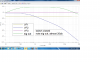
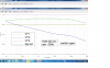
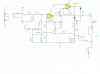
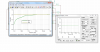
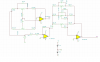
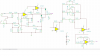
I may have stumbled on a method to control the audio peaks for front and back by adding a control voltage as seen in the attached screen shots
a simple switch and V- supply, add a pot for adjustment
 

Attachments

  • switch cv closed.png
    switch cv closed.png
    113.9 KB · Views: 225
  • switch cv open.png
    switch cv open.png
    135.6 KB · Views: 225
forgot the schematic

values etc need to be corrected?
 

Attachments

  • peak circuit w_switch.png
    peak circuit w_switch.png
    31.6 KB · Views: 230
Instead of messing up the time constant of 3.9M R16 slowly discharging 0.1uF C7 with your low value pot to change the threshold voltage of the Jfet, instead change the value of R5. When R5 has a low value then the Jfet is cutoff most of the time and the max signal level will be higher. When R5 has a high value then the Jfet will attenuate signals at a lower level.

The TL072 and most other opamps have a difficult job trying to drive a 600 ohm load. Their minimum spec'd load is 2k ohms.
The 1N4001 is a high current rectifier for 60Hz. It works poorly at audio frequencies. Use 1N914 or 1N4148 signal diodes instead.
 
Thanks will make changes.

Contemplating using a pot for R5 for adjustment purposes only.
The circuit will be the first stage
second stage = tone control or bandpass filter
3rd stage = a simple headphone amp using an op amp.
I posted a schematic but its called a cmoy amp. Got from DIY audio
**broken link removed**
have two different tone controls I am simulating but still looking at the BP filters.
 
Thanks for reminding me where the Baxandall 3-band tone controls circuit came from (National Semi LF353 datasheet). Lately I needed its frequency response graph and haven't looked at that datasheet for about 33 years.
 
I changed the value of R5 but not nearly the change of the pot in parallel of R16.
Will play with the 3 tone control circuit with the peak limit circuit as an input.
Found two different tone controls but feel maybe 3 band would be better?
 
The Baxadall looks better

ran a comparison and the Baxadall looks better
 

Attachments

  • baxadall comparision.png
    baxadall comparision.png
    98.1 KB · Views: 226
  • baxdall sch..png
    baxdall sch..png
    36.8 KB · Views: 243
BY Joe I think I got it

Here is hopefully the final design.
Just need to build two individual circuits.
 

Attachments

  • final hopefully.png
    final hopefully.png
    48.3 KB · Views: 245
Status
Not open for further replies.

Latest threads

New Articles From Microcontroller Tips

Back
Top