Continue to Site

Welcome to our site!

Electro Tech is an online community (with over 170,000 members) who enjoy talking about and building electronic circuits, projects and gadgets. To participate you need to register. Registration is free. Click here to register now.

  • Welcome to our site! Electro Tech is an online community (with over 170,000 members) who enjoy talking about and building electronic circuits, projects and gadgets. To participate you need to register. Registration is free. Click here to register now.

Hall effect water sensor advice needed

Status
Not open for further replies.

Ken1

Member
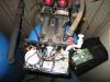
Hi, I have an iron filter and a water softener both of which use a hall effect sensor to meter water flow and trigger the regeneration cycle after a user set number of gallons of water have been consumed. The iron filter water usage sensor is now recording 1/2 the usage that the softener is recording. I took the unit apart where the rotor is plumbed in and cleaned it and checked the little rotor and it spins freely. Unfortunately this did not solve the problem. Any suggestions? Also, is it possible to plumb in an external hall effect water flow meter (like the ones on ebay) if the built in rotor assembly is defective? The red wire has 5V on it and the blue wire measures 1V. The iron filter is a Rainfresh model CAFE 948. I contacted tech support but did not get a satisfactory reply. The reply I got was to set it to regenerate every 3 days. This is too often and wasteful as my water has low iron content and I do not consume that large a volume of water; additionally my water usage varies considerably from day to day throughout the year. Also I live in a rural area and do not want to load up my septic tank with that much water. I have attached a photo of the iron filter's electronics.
 

Attachments

  • IMG_0811.JPG
    IMG_0811.JPG
    1.8 MB · Views: 160
Have you done a manual flow check to confirm which metering device (CAFE or softener) is telling the truth?

I haven't been able to find the CAFE 948 "Control Head" manual (referred to in the installation manual's trouble shooting guide) but the installation manual implies that you can set the frequency of the back flush according to water usage.

Once you've learned which unit is giving the correct flow rate and it is NOT the CAFE, could you adjust the back flush rate to match the actual flow rate?
 
Something is lying to you and that is pretty much a given. You are not concerned with flow rate but flow total, your meter is a totalizer. The Hall Effect sensor is a switch which generates pulses and so many pulses equal a given amount be it a quart, litre, gallon or other unit of liquid measure. We would call this a "K" Factor:
The axial design PRECISION TURBINE FLOWMETER is inherently linear within a known turndown range, typically 15:1, based on velocity of the measured fluid. The device has unmatched capability of precise and repeatable K-Factor generation based on the turning of the balanced rotor and the subsequently generated frequency pulse signal via the magnetic coil assembly, providing accuracy of +/-.15% with special calibration applied. Each pulse generated represents a discrete amount of volumetric throughput. Dividing the total number of pulses generated by the specific amount of liquid product that passed through the PTF determines the K-Factor.

Put in the simplest of terms, K-Factor is no more complicated than understanding that the meter will generate a specific number of pulses for every unit of product passing through it. If the user can detect the pulses, then it is a straightforward task to determine flow rate and totals. The K-Factor, expressed in pulses per unit volume, may be used to electronically provide an indication of volumetric throughput directly in engineering units.

That is about it in a nutshell. Would there be a simple way you could for example fill a 5 gallon bucket and see what you read? Time matters not only the volume of 5 gallons and which meter reads correctly. Most meters that totalize have dip switches allowing us to set a K factor or how many pulses will equal how much? I would guess your first step would be to find which unit is honest by running about 5 gallons into a marked 5 gallon bucket.

Ron
 
Hi, I checked the units out by filling a 5 gallon pail as suggested and the softener is correct as to flow rate and total gallons used. The iron filter displayed only 1/2 the flow rate and counted only 3 gallons used. The flow rate on these units displays to the nearest 1/10 gallon per minute while the total consumption is in whole gallons only. I could simply reset the iron filter to regenerate after only 1/2 the number of gallons that I currently have it set to. I am also interested in finding out what is causing the problem and fix it if possible.
 
Hi, I checked the units out by filling a 5 gallon pail as suggested and the softener is correct as to flow rate and total gallons used. The iron filter displayed only 1/2 the flow rate and counted only 3 gallons used. The flow rate on these units displays to the nearest 1/10 gallon per minute while the total consumption is in whole gallons only. I could simply reset the iron filter to regenerate after only 1/2 the number of gallons that I currently have it set to. I am also interested in finding out what is causing the problem and fix it if possible.

Just so I understand you are seeing the flow rate as well as totalized flow? Well anyway we know which is telling the truth and which is in error. I mentioned how sometimes units like this use dip switches to set the math functions. They look at the pulse count know what the K factor is I mentioned earlier for a specific transmitter and do the math based on that K factor. So many pulses equal a gallon. So without seeing things my guess is if they use dip switches something is set wrong to do the math functions. Since I don't have a book or manual for the iron filter I am unsure how it gets setup. I would, however, bet that therein lies the problem.

I did find this manual which explains the setup in some detail. You are setup according to this manual correct?

Ron
 
Last edited:
That is the correct manual for the iron filter. The display continuously cycles to show current time and date, last date of regeneration, peak water flow rate, current water flow rate, number of gallons per regeneration cycle, number of gallons left in current cycle, time of day regeneration takes place. I had another person watch the displays of both units while I was filling the 5 gallon pail. The electronics do not have a set of dip switches as can be seen in the photo I uploaded.
 
You would think with a phone call to these guys this could be resolved. Generally they use dip switches to set up the math for a known K factor number. Most flow systems and flow totalizers I have worked with in the past worked this way. The unit itself shows a pretty straight forward 3/4" Inlet / Outlet. I can fully appreciate your point of just setting the thing for 3 days as an example being a waste of water. They should be able to give you a solution for the problem and when you miss the target by about 50% that is a big miss!. I would get these guys back on the phone and ask for an explanation of the error.

Ron
 
Hi Ken,
Is it possible that the impellor had two magnets fitted to it so that it produced tw0 pulses per revolution but one of them has come off ? You could see if there is a manufacturers name and part number on the flow sensor and try to find the data sheet. You could then measure the output frequency for a known flow rate to determine if the fault is with the sensor or the electronics.

Les.

That's a real good theory. Strange how it is just about half.

Ron
 
For now I adjusted the meter to 1/2 the number of gallons per cycle. I will experiment with an external plumbed in hall effect flow sensor assembly when it arrives. As for the built in rotor it's built in too well to see how many magnets it has and I would have to figure out how to gain access to it and disassemble it without destroying it to check for 2 magnets and that would require disrupting water service for a considerable period of time.
 
Status
Not open for further replies.

Latest threads

New Articles From Microcontroller Tips

Back
Top