Electro Tech is an online community (with over 170,000 members) who enjoy talking about and building electronic circuits, projects and gadgets. To participate you need to register. Registration is free. Click here to register now.
Welcome to our site! Electro Tech is an online community (with over 170,000 members) who enjoy talking about and building electronic circuits, projects and gadgets. To participate you need to register. Registration is free. Click here to register now.
Oh ok that's great. If you want to work on more filters that's cool too, and now that we've done a couple like that we can look at another way to get the amplitude when we have real and imag in the numerator and real and imag in the denominator. I'll use RN and IN for numerator real and imag, and RD and ID for denominator real and imag.
For an equation thus:
(RN+IN*j)/(RD+ID*j)
we can calculate the amplitude like this:
Ampl=sqrt(RN^2+IN^2)/sqrt(RD^2+ID^2)
so that might make it a little easier for you to calculate the amplitudes of these more complex filters.
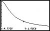
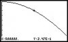
Well, now that you have a few formulas you should probably plot a couple of them. For example, plot the low pass filter without that extra resistor R2 and then plot it with the extra resistor, making the resistor somewhat comparable to the first resistor R1. You should then find the -3db point for both and also the passband gain, then compare these findings.
This should be interesting.
Oh ok that's great. If you want to work on more filters that's cool too, and now that we've done a couple like that we can look at another way to get the amplitude when we have real and imag in the numerator and real and imag in the denominator. I'll use RN and IN for numerator real and imag, and RD and ID for denominator real and imag.
For an equation thus:
(RN+IN*j)/(RD+ID*j)
we can calculate the amplitude like this:
Ampl=sqrt(RN^2+IN^2)/sqrt(RD^2+ID^2)
so that might make it a little easier for you to calculate the amplitudes of these more complex filters.
I guess I'm still not quite sure how I seperate the imaginary and real parts, given a circuit? I suppose that I solve it using nodal analysis, and then try to get the terms in the order of that first equation you listed? Or is that first equation just an example equation?
It's all in the grouping. Let me give a few examples...
A+B+C+D
Those four terms are all real, so the real part is A+B+C+D. They are all real because there is no 'j' multiplying any of them.
A+B+C*j+D
Here we have to group the terms that contain 'j' as imag and those that dont as real, so the real part is A+B+D and the imag part is C.
A+B*j+C+D*j
Here we have two terms that have 'j' multiplying them, and two that dont. The two that dont are real, and the two that do are imag, so the real is A+C and the imag is B+D.
A*j+B*j+C*j+D*j
Here everything is multiplied by j, so everything is imag and the real part is zero.
One way to look at it is we group all the 'j' terms together and that forms the imag part, and whatever is left over is real.
A+B*j+C*j+D*j
we can regroup this as A+j*(B+C+D) so A is real and B+C+D is imag.
When we have a numerator and denominator, we do the same thing except separately for each one.
(A+B*j+C*j)/(D+E+F*j+G*j)
we can regroup as:
(A+j*(B+C))/(D+E+j*(F+G))
and so real in the numerator is A, and imag numerator is B+C, and real in denom is D+E and imag is F+G.
Make sense?
Now you try one:
(A+B+C*j+D+E*j+1)/(F*j+G+H*j+3)
Find the real and imag in numerator, and real and imag in denominator.
I have produced the equations you wanted, and I've been trying to graph them but unfortunately I can't get MathCAD to graph anything! Have you had any experience with MathCAD? I'm trying to get my HP-50G to download the graphs on the PC.
I got my HP-50G to show the graphs, but only individually. I don't have a large enough span in order to plot them both. The problem is that with the 50Ω load, it reduces [LATEX]V_O[/LATEX] drastically down to the mV range. So I don't even see the latter graph, only the former one.
For some reason I still can't get MathCAD to graph anything!
There is something wrong with the denominator for your loaded filter. You'll have to go over that.
Also, try using 1k for R1 and 1k also for RL so that the load is comparable to R1. Once you do that, find the passband gain and -3db point for both filters and dont assume anything.
I have produced the equations you wanted, and I've been trying to graph them but unfortunately I can't get MathCAD to graph anything! Have you had any experience with MathCAD? I'm trying to get my HP-50G to download the graphs on the PC.
THIS LINE LOOKS OK:
[LATEX]V_O = \frac{V_{IN} R_L}{R_L + Z_R + R_L Z_R j \omega C}[/LATEX]
Seperate Real & Imaginary:
THIS LINE DOESNT:
[LATEX]\frac{V_{IN}^2 R_L^2}{R_L^2 + Z_R^2 R_L^2 Z_R^2 \omega^2 C^2}[/LATEX]
Calculate Amplitude:
SO THIS LINE IS NOT CORRECT EITHER:
[LATEX]Amplitude = \frac{V_{IN} R_L}{\sqrt{R_L^2 + Z_R^2 + R_L^2 Z_R^2 \omega^2 C^2}}[/LATEX]
Note in the second line you lost a variable again, and in the third line it comes back but it's not correct.
I think you should take one step at a time, so instead of separating real and imag parts and squaring all in one step, do the separation first and after that is completely done THEN do the squaring or whatever else is needed.
This site uses cookies to help personalise content, tailor your experience and to keep you logged in if you register.
By continuing to use this site, you are consenting to our use of cookies.