Electro Tech is an online community (with over 170,000 members) who enjoy talking about and building electronic circuits, projects and gadgets. To participate you need to register. Registration is free. Click here to register now.
Welcome to our site! Electro Tech is an online community (with over 170,000 members) who enjoy talking about and building electronic circuits, projects and gadgets. To participate you need to register. Registration is free. Click here to register now.
Ok, got all the components now That 4700µF is a scary looking one
Now all i need is to wait for my breadboard to come in the post so i can try the circuit out lookin forward to seeing if i will get it right! lol.
Just set up the 'fading' circuit with a 9v battery and it worked great!
But will all the components be safe with a 12v supply going through it? I know the LEDs i bought are 9-12v so im fairly sure they will be fine.
Also, the 'fading' is a little fast, i read in the adobe file that it is the resistor between pins 3 and 6 to ground that i should change to adjust it. But do i need a stronger or weaker resistor to make it go slower?
Howdy again! Actually, what it says is that changing that resistor will affect how dim the LEDs get before they go out. Is that what you mean? If you just want to adjust the rate at which they fade up and down, adjust the value of the 47k resistor between pins 2 and 7. Make it higher for slower and lower for faster. Even better, stick a 100k or so linear potentiometer in there with one leg to pin 2 and the wiper to pin 7.
All the components in the circuit will be fine with 12V, but remember that a 12V wall wart will give a no-load reading voltage of well over 12V. I mean, if you just plug the wall wart into the socket and measure its output when it's not powering anything, you'll get a reading of maybe 14 or 15V instead of 12V. The idea is that since they are unregulated, they "sag" the voltage when something draws a certain load through them. Say the adaptor is rated 12V @ 500mA--that means that it's expected to put out around 12V when some device is drawing 500mA through it. If the device pulls less, then the voltage will be higher.
Sounds weird, but it's true.
The point behind all this rambling is that the 12VAC adaptor is going to give you more than 12VDC after rectification and filtering already, and if the adaptor has a high amp rating, you could wind up with more than 15V going into your circuit. I don't think you will exceed the 1458's max supply voltage or max input voltages, although I haven't really crunched all the numbers.
What I'm saying is: I *think* you should be fine, but if it were me, I'd just try it (after making sure I had anyother 1458 on hand in case I was wrong).
Again, I hope somebody will correct me if I'm leading you down the garden path here.
Ok, i think i have run into my first problem...
I wanted to see what would happen if i was to give it 12v dc to 'simulate' what it would roughly be gettin after the rectification and filtering ( i know u said it will be more, but thats why i say roughly )
So i attatched it to a 12v dc adapter and the LEDs dont faid at all and stay on... But they still work fine with a 9v battery
So the LEDs are staying on at a constant brightness all the time? Sorry, when I simmed it I didn't have a model of the 1458 to try so I've simmed using a TL072 model instead. I might have a 1458 out in the workshop though--I may have to put one of these things together this afternoon to see what I can come up with and to get an idea of what it's doing in real life. I don't suppose you have a TL072 lying around to try instead of the 1458, hey?
The easy answer would be: use a 9VAC wall wart. I'm gathering that you don't have one, however. Anyway, I'll see what I can come up with later today. Sorry about the waiting. Have a wife, kid, and job to take care of first.
You forgot to tell us the forward voltage and how many LEDs you have.
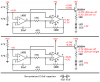
I crunched the numbers for two 1.8V red LEDs in series or one 3.6V white or blue LED.
I show the peak voltages.
1) With a 9.0V supply, the LEDs turn off completely and turn on with a peak current of 17mA.
2) With a 12.0V supply, the LEDs get very dim then turn on with a peak current of 40mA which might burn them out.
The 22uF capacitor must be non-polarized. It can be two 47uF polarized capacitors back-to-back. Maybe that causes your problem with the LEDs not turning off with a 12V supply.
Dang, yeah. I forgot to mention that when going to 12V you should change the 100Ω current-limiting resistor on the LEDs to at least a 330Ω to protect the LEDs.
If you don't have a 330Ω resistor you can put 3 100Ω resistors in series.
Torben
Edit: That'll just protect the LEDs though--I don't think it'll help with the always-on thing, unless it brings the LED current low enough to make the dimming visible.
Your "no-name" red LEDs don't have a datasheet. I will guess that their forward voltage is 1.8V.
I will also guess that you have two in series like in the schematic.
Hmmmm.... I can always buy more components if i need to?
Would that other TL072 chip be able to fix this issue? Since ill be buying a few more resistors from there i would like to save on postage
and what voltage LEDs would be desirable? Although the ones i have didnt frazzle out when they where on the 12v... I could also email the website i got them from to see if they can tell me what there voltage is?
Hmmmm.... I can always buy more components if i need to?
Would that other TL072 chip be able to fix this issue? Since ill be buying a few more resistors from there i would like to save on postage
I would not expect that the TL072 would fix it, no. . .it was just because that's what I simmed with and I was wondering about it. However, sims don't get everything right and can't really be trusted to tell you when things will work or not.
and what voltage LEDs would be desirable? Although the ones i have didnt frazzle out when they where on the 12v... I could also email the website i got them from to see if they can tell me what there voltage is?
You can actually run LEDs at pretty much any reasonable voltage, as long as you make sure the current running through them doesn't get high enough to burn them out. The simplest way to do that is to use a current-limiting resistor, such as the 100Ω resistor used in that schematic. You can calculate the needed resistor if you know the current demand and forward voltage of the LEDs but we're having to guess at what your LEDs' values are since there's no datasheet.
If you're ordering more parts, I'd recommend getting a value pack or grab bag of resistors so you will have various values to play with. Schematics often show what worked for the author; you will often need to tweak the values to get things to work for you depending on what your actual circuit ends up looking like.
You can use an LM7809 voltage regulator IC plus two capacitors to reduce the 12V down to 9V.
But my calculations show that when the supply is only 12V and two LEDs are in series and the timing capacitor is two back-to-back then it should work.
Try connecting three LEDs in series and in series with the 100 ohm resistor. Then try four LEDs.
Yup, worked for me, although when I built it a couple of hours ago I did have some differences in my circuit: I don't have a 1458 around and all my 3904s are in use. I used a TL082 and a 4401 instead. Also, I just used a 22uF non-polarized cap instead of the back-to-back 47uFs.
Worked fine anywhere from around 7 volts clear up to 18 (well, just under 18; I didn't feel like cooking my op amp). The fades got quicker and brighter as I boosted the voltage but it was perfectly happy at 12V. I threw in a third LED just to keep the current relatively safe (didn't bother with the resistor because I only had the thing running for less than a minute).
I don't have any ideas right now as to why blckscab is getting that result at 12V, but that will have to wait for after dinner. I never have any good ideas right before dinner.
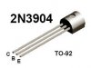
If the collector and emitter of the transistor are wired backwards then the transistor will conduct like a zener diode when it is supposed to be turned off.
The collector and emitter of BCxxx transistors are reversed from 2Nxxxx transistors.
I went back out to the shop and tried flipping the transistor with my power supply set to 12VDC. The LEDs stayed off. However, when I boosted the voltage to about 13-14V, the LEDs came on and stayed on. So that could be the problem: the 12VDC adaptor is probably not loaded enough by the circuit to get down to 12V, which would make a backwards transistor conduct like audioguru mentioned.
I just realized while writing the above paragraph that this didn't explain to me why the thing would have worked on the 9V battery, so I ran back out and tried it with the transistor backwards at 8, 9, 10, 11, 12, 13, and 14 volts. The results were as follows:
8V: No action from the LEDs (they just stayed off).
9V: Weak fading on the LEDs.
~9.5-~10.5V: Strong fading on the LEDs; working nicely.
11V: LEDs stayed off.
12V: LEDs stayed off.
~12.5V-14V: LEDs stay on.
With the above results, that might explain nicely why blckscab saw the thing working on the 9V battery, but the LEDs stayed on with the 12V adaptor.
Blckscab, can you try flipping the transistor? Given my above results it seems likely that your results could be explained by the transistor being backwards in the circuit.
im at work at the moment but i will try this out when i get back home and see what happens. I looked at a website to find out what legs of the transistor do what. 1 = collecter, 2 = base, 3 = emitter etc...
So maybe the website was wrong or ive done a silly mistake, but i am using a 2N3904 transistor like the one used in the 'fading eyes' adobe file
Edit:
also got this email from the website i buy my components from...
Hello Alex, the supply voltage for both these LED`s is exactly the same:
1.85v - 2.5v max @30ma. I hope this will help. Good luck with your project.
Kind Regards, Will.
This site uses cookies to help personalise content, tailor your experience and to keep you logged in if you register.
By continuing to use this site, you are consenting to our use of cookies.

") That 4700µF is a scary looking one
That 4700µF is a scary looking one