Electro Tech is an online community (with over 170,000 members) who enjoy talking about and building electronic circuits, projects and gadgets. To participate you need to register. Registration is free. Click here to register now.
Welcome to our site! Electro Tech is an online community (with over 170,000 members) who enjoy talking about and building electronic circuits, projects and gadgets. To participate you need to register. Registration is free. Click here to register now.
Well because the second part of this project actually has a window comparator circuit. What I am afraid is that if my circuitries are single supply, it may affect the secondary part of the project.
Hi AudioGuru,
Well because the second part of this project actually has a window comparator circuit. What I am afraid is that if my circuitries are single supply, it may affect the secondary part of the project.
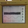
Well I tried out the schematic below. I replaced the 10uF to 10nF at the sine wave circuit because my 10uF is a electrolytic capacitor. However, I am able to get an sine wave and triangular wave with a DC offset in the input of the LM339. But my inverted sine wave shows an almost DC line.
Attachments
Sine & Inverted Sine [Single Supply].jpg
729 KB
· Views: 478
Working Sine wave with LM339 output [Single Supply].jpg
ANY opamp will work perfectly with a single supply if its input is biased at half the supply voltage.
Your sine-wave inverter opamp is not working properly.
It has a +12V supply which is fine and its (+) input is biased at +6V (half the supply voltage) which is fine.
Its output should be the same level and DC voltage as the input (I do not know why its input is only +5VDC instead of +6VDC) but its output is only about +2V instead of +6V and is as low as it can go.
Why did you use such a low value of 10nF (0.01uF) for C3? Then it cannot pass 50Hz or 60Hz into the 10k resistance of R5. A 10uf electrolytic capacitor is fine if you connect its polarity correctly. The pot is at 0VDC and R5 is at +6VDC.
I made a mistake. The value of the capacitor from the pot feeding the non-inverted sinewave to the 100k bias resistor and the inputs of the comparators should be 220nF (0.22uF).
Is there any way to solve the issue of the inverting sine wave?
My only concern is that a electrolytic is a 'DC' Capacitor. If I were to connect an inverting signal across it, then at the negative cycle of the sine wave, the capacitor will be in the reverse polarity? Correct me if I am wrong.
Why is it 220nF? Is it due to the low frequency of the sine wave?
When I connected up the 200nF, it actually affect my triangular wave. I doubt it is suppose to affect
The circuit that makes the inverted sinewave is a simple and standard inverting opamp. As I explained previously, " A 10uf electrolytic capacitor is fine if you connect its polarity correctly. The pot is at 0VDC and R5 is at +6VDC" so the capacitor ALWAYS has only one polarity.
Without a signal the (+) input of the opamp is +6V and R6 applies 100% negative feedback at DC causing the output to also be +6V but your output is wrongly at only +2V which is as low as it can go.
220nF feeding 50Hz to the 100k bias resistor (and the very high impedance inputs of the comparators) has a cutoff frequency of 7.3Hz so it passes 50Hz perfectly. It is a simple calculation.
The sinewave should not affect the triangle wave. If it does then maybe the power supply is missing a bypass capacitor to ground.
Sorry if I dont get your meaning but why the pot has a potential of 0v? If the grid voltage is coming in from the pot, it should have a P.D. Sorry, I am a starter in this field.
So if that's the case, is the schematic okay?
As for the inverter sine wave, could it be that it's the IC chip problem?
For the triangular power supply, I thought the 10uF capacitor should do the trick already?
The grid voltage is WAY too high for this circuit. A much lower sinewave signal is coming from a stepdown transformer that is also connected to 0V. The function generator should also be connected to 0V.
The coupling capacitor PASSES the signal so the same signal is at each end of the capacitor. But the capacitor has 6VDC across it.
Why is it that the both capacitor of the 10uF and 220nF is different? Since the sine wave is 50Hz, shouldnt it be the same capacitor value?
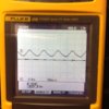
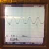
However, just to check with you, these're my sine wave waveform before connecting it to LM339. How do you rectify this issue cause all the sine wave has different RMS value. The value in the waveform are all RMS.
You need to learn the simple formula for calculating the value of a coupling capacitor at -3dB: 1 divided by (2 x pi x R x C).
You changed my copy of your schematic. I had C3 as 10uF feeding the 10k resistance of R5 (-3dB at 1.6Hz) so 50Hz is not attenuated but now you have 100nF feeding 30k (-3dB at 53.3Hz) so 50Hz is attenuated more than -3dB and also has phase shift.
I had 220nF feeding 100k (-3dB at 7.27Hz) so 50Hz is not attenuated. But 1uF would produce the same small amount of phase shift as the 10uF feeding the 10k.
Hi,
Sorry but may I know why do we take at -3db? and to prevent attenuation, am I able to use R5 = R6 = 1M ohms, C3 = 100nF
Given that R5 and C3 =1M ohms and 100nF, Fc = 1/(2*PI*1M*100n) = 1.6Hz,
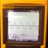
The waveform that I got is the one below. The dash on the waveform indicate the bias line. Both the +/-Vpeak experience clipping
In addition, why must the minimum frequency at -3db so that 50Hz is not attenuated.
Sorry, my lecturer never taught us about attenuation before...
The formula I provided gives an attenuation of -3dB (half the power) which is a barely audible drop of sound level. A light is a little dimmed.
If the frequency is calculated to be 1/10th (5Hz instead of 50Hz) then the attenuation is very small.
The RATIO of R5 and R6 set the gain of the inverting opamp. If their values are from 2k ohms to about 200k ohms then the ratio and therefore the gain stays the same.
The output is clipping because the gain of the opamp is 1 and its input signal level is too high.
Your 'scope is useless because it does not show where is 0VDC.
We are not talking about a power supply decoupling cap which is a filter to ground. Instead we are talking about a coupling cap that couples (passes) a signal. A capacitor has reactance (resistance to AC). A lower frequency and/or a lower load resistance needs a higher value coupling capacitor.
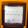
So I was able to generate a PWM signal. However, when I pass it through the IR2113, the Ho only shows a constant DC line while the Lo shows the PWM signal. Anyone has any idea on why the high side is unable to work?
The waveform shown below are taken before connecting to the IGBT, [After R9, R10]
The red line indicates the 0V reference line
This site uses cookies to help personalise content, tailor your experience and to keep you logged in if you register.
By continuing to use this site, you are consenting to our use of cookies.

![Sine & Inverted Sine [Single Supply].jpg](/data/attachments/71/71624-79cd09d91f9fc0c6dd585dbcf66ec07c.jpg)
![Working Sine wave with LM339 output [Single Supply].jpg](/data/attachments/71/71625-e8e4d91777e92ff15ce97d2adc4b86f8.jpg)
![Triangular Wave [Single Supply].jpg](/data/attachments/71/71626-f5f588fbb751c5d3ef154c93387e34bf.jpg)
![Sine & Inverted Sine [Single Supply].jpg](/data/attachments/71/71627-79cd09d91f9fc0c6dd585dbcf66ec07c.jpg)