Continue to Site

Welcome to our site!

Electro Tech is an online community (with over 170,000 members) who enjoy talking about and building electronic circuits, projects and gadgets. To participate you need to register. Registration is free. Click here to register now.

  • Welcome to our site! Electro Tech is an online community (with over 170,000 members) who enjoy talking about and building electronic circuits, projects and gadgets. To participate you need to register. Registration is free. Click here to register now.

Fuel gauge adapter

Status
Not open for further replies.

jelliott

Member
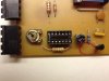
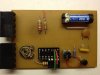
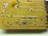
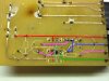
If anyone is still paying attention to this thread... I built the circuit shown in Post #4 above by Ericgibbs, and it's not working. It looks like it's probably a problem with the chip, but I'm hoping some of the knowledgeable people on this forum may be able to help me confirm that. I've got 12 V, 2.5 V, and ground in all the right places, but with a 5 V input I'm getting an output > 7 V instead of 0 V. When I adjust the potentiometer that I'm using in position R2 the erroneous output is unchanged, which is what leads me to believe that the chip must be at fault. Any thoughts? (For what it's worth, the chip I'm using is an NTE7144, which is the cross-reference Mouser gave me when I searched for CA3140; as far as I can tell this is a totally legit cross-reference, but since most of my electrical engineering knowledge is strictly theoretical, I'm curious if I've inadvertently made some kind of op-amp cross-referencing faux pas.)

Thanks,
Joe Elliott
 
I'm new to this forum, so I'm not sure whether I'm better off replying to a thread that's been dead for some time or starting a new (and potentially redunant) one, so I've gone ahead and done both. Anyway, I built a circuit based largely on Post #4 in "Inverting amplifier," and it's not working. It looks like it's probably a problem with the chip, but I'm hoping maybe it's something I've done wrong that I can fix this weekend.

I've got 12 V, 2.5 V, and ground in all the right places, but with either a 5 V or 0 V input I'm getting a constant output > 7 V. When I adjust the potentiometer that I'm using in position R2 the erroneous output is unchanged, which is what leads me to believe that the chip must be at fault. Any thoughts? (For what it's worth, the chip I'm using is an NTE7144, which is the cross-reference Mouser gave me when I searched for CA3140; as far as I can tell this is a totally legit cross-reference, but since most of my electrical engineering knowledge is strictly theoretical, I'm curious if I've inadvertently made some kind of op-amp cross-referencing faux pas.)

Thanks in advance,
Joe Elliott
 
hi,
How is the Strobe pin on the NTE, pin #8 connected.?
 
I've got 12 V, 2.5 V, and ground in all the right places
Have you checked the datasheets for both the CA3140 and the NTE7144 to make sure that their pin-outs are identical? It's not unknown for so-called equivalents to have similar functionality but different pin-outs.
When I adjust the potentiometer that I'm using in position R2 the erroneous output is unchanged
That does sound as though the chip may be faulty, if its connections are all correct. The IC has a mosfet input and mosfets can be damaged by static electricity when touched etc.
 
hi Joe,
I have merged your two Threads, please do not open two threads on the same topic, it causes confusion with the replies.

E
 
It's not. Pins 8, 5, and 1 are floating. Is that my problem?

(And yes, I've verified that the pinout is as I expected.)

Thanks again.

hi,
Pins 1 and 5 are used for offset Null, optional.
The datasheet doesnt give any guidance on the Strobe pin, so I would try pin 8 via 1K to +V and check the output, if the same try, pin via 1k to 0V.

Lets know what you get.
 
I would try pin 8 via 1K to +V and check the output, if the same try, pin via 1k to 0V.

I don't have any 1k ohm resistors available here (I'm visiting family for Thanksgiving--it's my brother's electric car that's supposed to have a working fuel gauge before I leave tomorrow evening), but I tried this with 10k ohm resistors, and output was unchanged.
 
I don't have any 1k ohm resistors available here (I'm visiting family for Thanksgiving--it's my brother's electric car that's supposed to have a working fuel gauge before I leave tomorrow evening), but I tried this with 10k ohm resistors, and output was unchanged.

Hi,
If possible post a clear picture of the pcb, front and back, we can check your wiring.
 
Hi,
If possible post a clear picture of the pcb, front and back, we can check your wiring.

The circuit in question is on the lower half of the board in these photos. From top to bottom the four external connections on that half of the board are +12 V, output to instrument panel (5-0 V = 0-100% state of charge), input from battery monitor (0-5 V = 0-100% SOC), and ground. IC mounting is a little unorthodox because (if you couldn't guess) in my hurry to get this built in time for the Thanksgiving holiday, I designed the PCB with the IC mounting points backwards. The unused pins in the IC socket are meant to be used to add resistors (or in this case a plane wire to eliminate variables for troubleshooting purposes) in parallel with the potentiometer on the output (which is there for fine tuning, since bench tests of the gauge indicated that it'll read 100% at more like 0.5 V than 0 V). (The other potentiometer is in place of R2 in the aforementioned schematic, to fine tune feedback resistance.)
 

Attachments

  • photo 4.JPG
    photo 4.JPG
    553.3 KB · Views: 195
  • photo 2.JPG
    photo 2.JPG
    496.7 KB · Views: 196
  • photo 3.JPG
    photo 3.JPG
    587.8 KB · Views: 190
hi,
Trying to make sense of your inverted layout.:D

Please post the voltage measured on each IC pin of the OPA relative to 0V
 

Attachments

  • photo 3.JPG
    photo 3.JPG
    285.6 KB · Views: 197
Last edited:
Please post the voltage measured on each IC pin of the OPA relative to 0V

IC pin voltages as follows:
2: 3.25 V
3: 2.48 V
4: 0 V
6: 8.4 V *
7: 12.67 V

Supply voltage was 12.67 V. Input from the battery monitor was 5.12 V.

*: 8.4 V was the final measurement on the output pin. Initially it was around 5 V as before but, more interestingly, when the PCB was disconnected from the instrument panel, the output dropped to 1.34 V, which would almost be correct, except when I tried adjusting the R2 potentiometer it never did come down to the expected ~0 V, and only when I cranked the pot almost all the way in one direction did it increase a bit.
 
hi,
I suspect your problem is not on the pcb, but how it is connected externally.
 

Attachments

  • photo 3.JPG
    photo 3.JPG
    291.1 KB · Views: 170
If I attach the input to 0 V instead of to the battery monitor, and leave the output floating instead of connected to the gauge, the circuit behaves seemingly correctly, with an output of ~5 V that I can adjust with the R2 potentiometer, as intended. When it's connected to the gauge, the needle comes off the off-scale-low stop and reads roughly "empty," as intended, except that it doesn't respond to R2 adjustment, and the actual voltage on the PCB output/gauge input had jumped up to ~7 V.

It seems as though the gauge just flows too much current for the NTE7144 to handle. Is there some alternative (or perhaps an addition to the circuit) that will accomodate higher currents?

Thanks again!
 
What type of gauge is it?. A cross field type draw about 20-25Ma.
 
Last edited:
I'm not sure what type of gauge it is, but it draws about 90 mA when the input is connected directly to 0 V. It's the stock fuel gauge in (what was) a 1980 Renault 5, for what that's worth. It has a total of three terminals; +12 V, 0 V, and the input. It reads "full" with a 0.6 V input and "empty" with a 5.3 V input (that's when 12 V is actually 12 V; at 13 V supply voltage those full scale inputs are 0.7 and 6.0 V, respectively).

Is the solution to my problem perhaps as simple as a resistor between the PCB output and 0 V, to give the current somewhere to go so the op-amp chip can produce the desired voltage without having to absorb all the current that such a voltage drop across the gauge necessitates?

hi,
Would say a 'load' resistor is required at the input to the PCB circuit. Choose a load resistor value that gives the required voltage range from Full to Empty
 
Would say a 'load' resistor is required at the input to the PCB circuit. Choose a load resistor value that gives the required voltage range from Full to Empty

I'm a little confused. It's not immediately apparent to me what effect(s) a resistor on the input is going to have on the circuit's output, or how to size it.
 
I'm a little confused. It's not immediately apparent to me what effect(s) a resistor on the input is going to have on the circuit's output, or how to size it.

hi,
Measure the resistance of the tank sensor at full and empty and post the values.
 
Measure the resistance of the tank sensor at full and empty and post the values.

I don't have a tank sensor in the conventional sense of a float attached to a potentiometer. It's an electric car with a battery monitor device (Curtis model 933, for what that's worth) that provides a 0 to 5 V analog signal in proportion to the batteries' state of charge (0 to 100%). So I don't think I can measure a meaningful resistance across it.
 
Status
Not open for further replies.

Latest threads

Back
Top