Continue to Site

Welcome to our site!

Electro Tech is an online community (with over 170,000 members) who enjoy talking about and building electronic circuits, projects and gadgets. To participate you need to register. Registration is free. Click here to register now.

  • Welcome to our site! Electro Tech is an online community (with over 170,000 members) who enjoy talking about and building electronic circuits, projects and gadgets. To participate you need to register. Registration is free. Click here to register now.

Friction Clutch for Lever Ideas?

Status
Not open for further replies.

dknguyen

Well-Known Member
Most Helpful Member
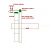
I'm making a lever-type throttle switch using the shaft of a potentiometer. The far side of the shaft is going to be supported by a bearing (ball or plain) of some kind. I am having trouble figuring out how to make a friction clutch so it stays where it was left. The safest and most compact way I've figured so far is to do something with that supporting bearing itself.

So...how do modify a bearing so it can rotate smoothly (nice smooth, wet, feel for the lever) but have it so there is enough friction so it stays put when released? Press-fit plain bushings seems like a bad idea. Ball bearings with some heavy grease or something (but then the grease might get all over the nearby PCBs).

I guess another idea is to clamp a piece of rubber against the sidewall and a shaft collar so that the shaft has to force the collar to rotate against the friction of the piece of rubber. But this requires a sufficiently long pot shaft which I don't have (the potshaft is already very short and there's barely enough room to run it through the width of the sidewalls and lever arm).
 
Last edited:
How about a simple press fit bushing? The main problem being that you'd need pretty high precision bushing and shaft clearances to get dependable friction. If the bushing is made of phosphor bronze and perhaps a second bushing is permanently mounted to the shaft and it's phosphor bronze then you have two beautifully smooth moving surface against each other but will hold very well. Phosphor bronze bushing tend to come impregnated with penetrating oils which means they never have to be lubricated, and if the bushings are smooth it will feel like pure silk when you turn the knob.
 
I'll look into that...see if I can't find a bronze bushing to mount to the shaft.

SEcond problem. The lever is basically a 4M threaded rod (well, not really, but something that is M4 female threads has to be able to screw onto the lever). And it needs to connect in some way to the potentiometer shaft. Ideally, I'd get a 1/4" bore shaft collar (because that is the diameter of the pot shaft) that uses M4 setscrews (preferably two, one for the clamping and I can use the second to connect the threaded rod to). But finding a metric-inch mix-matched shaft collar is really hard, let alone that a M4 sized setscrew is unusually small for a 1/4" bore! I'm afraid of drilling into the curved surface of the shaft collar for another hole because it is curbed and the shaft collar is so small.

I could...get a 1/4" bore setscrew collar (which seem to use 10-32 screws) and then use a 10-32 male-to- 4M female hex raiser as a setscrew which I could then screw the 4M threaded rod into...but haven't found a raiser like that yet.

Perhaps I should just get a 1/4" bore 10-32 setscrew collar and green loctite that to the pot shaft (rather than using a setscrew), and then file away the setscrew hole just a bit (the major diameter is 1mm too large for 4M threaded rod, but the minor diameter is 0.2mm too small) then just place the threaded rod into that hole and then epoxy it into place.

I've also looked into finding solid rod link ends (not ball-link rod ends) that have a 1/4" bore but an M4 thread...same problem, also hard!

Oh, and the assembly is very narrow. So the connection method can't be too wide "no more than 6-8mm really).
 
Last edited:
quote dknguyen "I guess another idea is to clamp a piece of rubber against the sidewall and a shaft collar so that the shaft has to force the collar to rotate against the friction of the piece of rubber. But this requires a sufficiently long pot shaft which I don't have (the potshaft is already very short and there's barely enough room to run it through the width of the sidewalls and lever arm). "

Instead of rubber consider using thin cork like used for a gasket. If there is a Radio Shack near you most of their pots have a long shaft on them.

Or use a "wave washer" Products | Fastenal Hobby shops that sell RC cars have a lot of neat stuff like this that may give some ideas. They may even have a throttle assembly you could adapt.
 
I usually use rubber o-rings for stuff like that. You can notch the shaft and use an o-ring inside a tube, to give a friction fit.

You can also just wrap the o-ring around the shaft 1 or more times, and anchor the other end of the o-ring to something (like a screw head). The tension adjusts the friction. Then a touch of grease, vaseline etc and it should last for years.
 
Actually I have a very specific potentiomter in mind because of it's price and construction. So the shaft length is limited to be quite short. The friction problem seems to have enough solutions for now, all of which would probably work. The real problem seems to be how to mount a threaded rod as a lever onto a potentiomter shaft!

I'm basically looking for something like this:
**broken link removed**

But in the dimensions I need which are mainly 1/4" bore, M4 hole on the flat side, and less than 8mm in thickness. How much do machinists charge to get about 8 of these made? Anyone have an idea at all?
 
what about some arrangement as shown?
 

Attachments

  • friction bearing.JPG
    friction bearing.JPG
    13.9 KB · Views: 300
Actually I have a very specific potentiomter in mind because of it's price and construction. So the shaft length is limited to be quite short. The friction problem seems to have enough solutions for now, all of which would probably work. The real problem seems to be how to mount a threaded rod as a lever onto a potentiomter shaft!

I'm basically looking for something like this:
**broken link removed**

But in the dimensions I need which are mainly 1/4" bore, M4 hole on the flat side, and less than 8mm in thickness. How much do machinists charge to get about 8 of these made? Anyone have an idea at all?


whay dont you think about a coupling it itself will work as a friction torque device too?
 
whay dont you think about a coupling it itself will work as a friction torque device too?

Sorry. I didn't understand this last sentence. I'm trying to go for as few parts as possible (mainly because I'm trying to keep the parts I have to get made as simple and cheap as possible) which is one reason I can't make all the slots to stick in the springs and tension bars and all that. That's the main reason I was trying to go more for a friction device in the support bushings or on a disc that a collar mounted to the shaft rubs against.

I'm not sure what the gear in your diagram is for. I am not trying to couple a gear or wheel to the potentiomter shaft. I am trying to couple a lever/handle to make something like this:
**broken link removed**
 
Last edited:
I usually use rubber o-rings for stuff like that. You can notch the shaft and use an o-ring inside a tube, to give a friction fit.

You can also just wrap the o-ring around the shaft 1 or more times, and anchor the other end of the o-ring to something (like a screw head). The tension adjusts the friction. Then a touch of grease, vaseline etc and it should last for years.

By notch, do you mean a small groove that runs along the entire circumference of the shaft that the O-ring sits in? If so, I think I see what you're getting at. I don't have the equipment or skill to do directly modify any shaft (let alone one that is already on the potentiomter). If I did...I'd probably just square the darn shaft or custom-make my own shaft collar and be done with it!

RIght now, I'm leaning towards some disc-type friction clutch method using wave washers since it seems simple enough to just throw them on the shaft.
 
Last edited:
may be my understanding of your discription was wrong, what i mentioned on the diagram is a short of ratchet for with the gear is used.
 
Oh, you're talking about a ratchet device rather than a friction clutch. I'm avoiding ratchet devices so you can have very fine control (which is preferred when using the lever for collective control to hover a helicopter.)
 
Actually I have a very specific potentiomter in mind because of it's price and construction. So the shaft length is limited to be quite short. The friction problem seems to have enough solutions for now, all of which would probably work. The real problem seems to be how to mount a threaded rod as a lever onto a potentiomter shaft!

I'm basically looking for something like this:
**broken link removed**

But in the dimensions I need which are mainly 1/4" bore, M4 hole on the flat side, and less than 8mm in thickness. How much do machinists charge to get about 8 of these made? Anyone have an idea at all?

How about these? McMaster-Carr

As far as changing the set screw to a metric size. You need access to a drill press and drill press vise.
1. Put a #21 drill(if the original thread is 10-32) in the chuck.
2. Put the drill into the set screw hole and lower both down until you can secure the collar in the vise.
3. Drill through the original set screw hole and through the opposite side of the collar with the correct Metric tap drill ( find tap drill size here
https://www.engineersedge.com/manufacturing/metric-iso-tap-drill-chart.htm)
4. Repeat #2 using the metric tap drill, but turn collar over so metric side is up.
5. Start metric tap in hole by putting tap in chuck BUT ONLY TURN CHUCK BY HAND!! DO NOT - DO NOT TURN ON POWER TO DRILL PRESS!!!
6. Finish tapping by hand.

There a a number of 4mm thread sizes thats why I gave the link to the tap drill sizes so you can pick the right one.

I don't know your experience with metal working so thats why I did it by numbers. Don't mean to offend you if you do this kind of work.
 
Ahh, still working on the heli DK? Yes, definitly friction bushings, I can think of nothing else that will give you the same feel, problem is vibration tends to affect things heavily.
 
Last edited:
Not offended at all...my mechanical skills, particularly shaping materials sucks hardcore. It's just difficult for me sometimes to justify getting the equipment to do it myself vs paying to have it done since I don't do very much mechanical stuff.

I've actually moved from Helis to sailplanes...just so much more efficient and longer flight time...and cheaper (batteries!) and the control electronics are also less demanding (so again, they're cheaper). Just gotta add spoilers, flaps, and/or airbrakes...then the landing is much more heli-like in that it is well controlled. No more ballistic landings lol. It's not as I would like, but because the sailplane is a very large foam one (if I go composite airframe I might as well get a heli!) it doesn't have to be exactly as I want it because foam...is not forever lol.

I'm heavily revisiting building my own RC transmitter because I've found a source for the joystick gimbals (3-axis gimbals nonetheless!) and am now willing to spend the money to get them. It's just going to make things easier in the long run. No channel limits like those in hobby RC systems and I can program exactly how I want the model to react to the control signals in C rather than fumbling with mixing configurations like those on an RC transmitter. And of course, a data downlink that won't interfere with the uplink so I can display flight status on the transmitter (yup! a touchscreen! the one I found is easy to program too!). It's the best I can do without learning how to make my own video overlay which seems to require intense FPGA graphics type stuff.

This lever in particular is for the RC transmitter. It's not onboard the model. I wanted multiple throttle levers however (the 3-axis joystick controls pitch roll and yaw). But for some reason fader-type throttle levers are seriously overpriced for what they are (single-axis gimbals- dead simple to make). They actually cost more than most 2-axis joysticks! I also have some other requirements so I'm trying to make my own. Ends up being considerably cheaper...as long as I need enough of them.

These mechanical problems I have on the transmitter are simple though compared to the ones I have in the aircraft. Primarily how and where to mount the pitot tube and AOA/sideslip sensors, and how to construct the AOA/sideslip sensor. Throwing an extra $200 at the problem would easily plow through these mechanical difficulties I am having with the transmitter. Takes quite a bit more $$$ to plow through where to mount a pitot tube and AOA/sideslip sensors when the wingtip is too vulnerable, difficult to modify and assymetrical wrt to the airframe. But the nose of the sailplane has a giant propeller disc on it that disrupts airflow everywhere else on the plane...at least when the propeller is running. Even more daunting is how to cheaply construct an vane AOA/sideslip sensor like this:
https://www.electro-tech-online.com/custompdfs/2010/01/ABprobe.pdf
how on earth would you simply, reliably, and accurately mount the shafts of both wind vanes to a center shaft like that?! while also providing bearings for rotation of the wind vanes?! and where would you stick the angular sensors for the vanes?!
 
Last edited:
RIght now it's looking like this support bracket fitted with that displayed potentiometer. If I can get the displayed shaft collar customed (and the company apparently does custom parts and mods with no minimum order...but how much is something they have to get back to me about) so the dimensions are a bit different, it can clamp around the shaft collar and the threaded rod can screw in as the lever. I got some aftermarket RC transmitter gimbal stick ends that can screw onto the threaded rod to give me real handles. Right now, I can accomodate the cost of the bracket. But the cost of the the collar is going to put me overbudget. I don't know how much it is yet though...I'd be thrilled if I could get it for $15 a collar which is super unlikely.
 

Attachments

  • Lever.jpg
    Lever.jpg
    615.6 KB · Views: 359
Hi dknguyen,
An easy way to make a friction disk for a lever actuated pot arm is


  1. make the lever arm which will go on the inner part of the pot shaft
  2. make a disk that is a pressfit on the shaft and put some rubber/leather on the face.
  3. make a sliding disk that will slide on the pot shaft that is spring loaded and adjustable then a bolt/set screw can be used for the tension.
This would be the easiest and strongest way and with having adjustable tension you could set it to overcome any vibration. Below is a paint mockup of what I mean.

spring loaded pot pic.JPG


Cheers Bryan
 
Last edited:
Hi dknguyen,
An easy way to make a friction disk for a lever actuated pot arm is


  1. make the lever arm which will go on the inner part of the pot shaft
  2. make a disk that is a pressfit on the shaft and put some rubber/leather on the face.
  3. make a sliding disk that will slide on the pot shaft that is spring loaded and adjustable then a bolt/set screw can be used for the tension.
This would be the easiest and strongest way and with having adjustable tension you could set it to overcome any vibration. Below is a paint mockup of what I mean.

View attachment 37855


Cheers Bryan

Oh i see. I don't have enough room for that on the tip of the pot shaft for something like that since the shaft isn't long enough to make it far enough past the sidewall. But I do have plenty of room on the otherside of the shaft at the root - the mounting threads for the potentiometer are much longer than the sidewall is thick so there's an extra 5-6mm of screw thread there where I mount the lever onto. I can flip your assembly around (minus tension screw) to the other end of the pot shaft. I can place spring washers or springs over that unused threaded area so that they push off of the sidewall that the pot face is mounted to to force a piece of friction material against the lever arm (or rather, the shaft collar the lever arm is mounted to). No variable tension screw adjustment, but if I use washers I can cram more into there until I get the force I want.

Or a slight mod could turn it into a tension adjustment nut instead of a tension adjustment screw. 3/8-32 nuts are a strange thread size though.
 
Last edited:
What ever you do, you have to watch putting too much spring pressure on the pot shaft. If you load it too much you risk breaking the resistance disk in side the pot, or wearing it too much.

How many of these are you talking about making?
 
What ever you do, you have to watch putting too much spring pressure on the pot shaft. If you load it too much you risk breaking the resistance disk in side the pot, or wearing it too much.

How many of these are you talking about making?

Four for immediate use, 8 in total.
 
Status
Not open for further replies.

Latest threads

Back
Top