AtomSoft
Well-Known Member
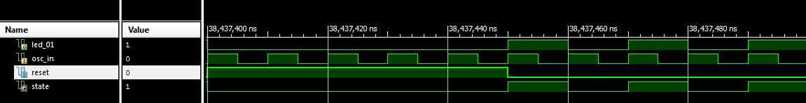
Ok i know im posting alot here but figured out i can implement a internal signal to use instead of the actual pin. This way i can leave it as OUT and not INOUT and also not have to process it:
Im sure i can also use BIT instead of STD_LOGIC but heh its ok i assume
Code:
entity BlinkLed is
    Port ( LED_01 : out  STD_LOGIC;
           OSC_IN : in  STD_LOGIC;
			  RESET : in STD_LOGIC);
end BlinkLed;

architecture Behavioral of BlinkLed is
	signal state : std_logic;
begin

	process(OSC_IN, RESET) is begin

	if(RESET = '1') then
	  state <= '0';
	elsif(rising_edge(OSC_IN)) then
	  state <= not state;
	end if;

	end process;

	LED_01 <= state;

end Behavioral;
Im sure i can also use BIT instead of STD_LOGIC but heh its ok i assume
Attachments
Last edited:

