Continue to Site

Welcome to our site!

Electro Tech is an online community (with over 170,000 members) who enjoy talking about and building electronic circuits, projects and gadgets. To participate you need to register. Registration is free. Click here to register now.

  • Welcome to our site! Electro Tech is an online community (with over 170,000 members) who enjoy talking about and building electronic circuits, projects and gadgets. To participate you need to register. Registration is free. Click here to register now.

FM transmitter WASP -oscillator working ,rf output stage not working

Status
Not open for further replies.
So why is the last stage anyways? Is'nt it reducing the output instead of amplifying it?Please correct me if I am wrong.

hi,
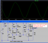
You asked to see whats on the collector of the oscillator, not the output of the oscillator which is on the emitter of the osc.
The output stage is a power amp.
 
if we see 2 stage fm transmitters,the first stage is an audio amplifier and the second stage is an rf oscillator.And the antenna is usually connected at the collector of the rf oscillator.But in this case we have an added rf output stage and the collector is connected to the output of this transistor.
Hence I wanted to know what is the advantage in this case?from graphs(Voltage at oscillator) it shows that voltage at the osc output >> voltage at the rf output stage.

But the LED power meter circuit by colin55 works on "ac voltage peak detector" rather than a power meter.If the ac signal does'nt have enough amplitude,the output LED of the meter will not glow even though the transmitter may be delivering more power(i.e. Voltage less ,current more which you say in this case).And hence I think I am getting no LED glow in this case.

From the webpage of the author(after reading it again) , I came to know that the rf output stage helps in frequency stability when using this transmitter as an hand-held microphone.

You say that this stage is a power amplifier.How do I calculate the power at the oscillator stage and the power at the rf output stage.And by power you mean the power delivered to the antenna right?how to calculate that?
 
Last edited:
Hey,
As I said that the oscillator is working ,I tried tuning the oscillator on the radio and successfully tuned it at 102Mhz.As previously said LED power meter LED glows on collector of first stage but doesn't glow at the RF output stage.But taking into consideration that rf output stage is working as a power amplifier ,and the explanation given by me in previous post,I don't expect LED power meter's led to glow.I wish if users to comment on validity of my explanation.

Also now I am using 3V supply from 2 AA size batteries.But the range is very less works only if the transmitter is around 20-30cm from the transmitter.I am using an antenna of 15cm.I tried using 30 cm antenna but the range didn't change.Also the output is clear only when I speak slowly and very softly.The author says that it can be used as an hand held microphone and considering 170cm ,I think it is bit too long for a hand held microphone.Sir could you comment on increasing range without increasing length of antenna?

Also if I speak normally the output from radio is very distorted and if I whisper and increase the volume from the radio,it comes very clear?Should I decrease the resistance from the microphone to VCC or the coupling cap to audio stage(which I guess is not a problem as same thing said in a whisper is audible) ?

Also sir,would the output from transmitter increase if I connect from the output of the collector of the oscillator instead of the emitter of the oscillator to the RF output stage?
 
Last edited:
hi savvej,
I estimate the RF power to be about 5mWatt.!

I would ask the 'designer' of the transmitter about any changes that may improve it.

The Transmitter designed by 'audioguru' should give better performance.
 
My FM transmitter simulates and works well. A quarter-wave whip antenna is 80cm long and is 75 ohms.
My output amplifier is tuned and has a nice big output level:
 

Attachments

  • FM transmitter output power.PNG
    FM transmitter output power.PNG
    33.8 KB · Views: 1,100
Thanks very much for your reply sir and schematic too.

What are the possible faults in this circuit?
Sir for your circuit,could you plot waveforms at oscillator output and rf out on same plot?
And how to calculate power delivered to antenna?

And as I told in my previous post,when I whisper the audio is clear,but as I speak normal,the audio distorts a lot.
Anything you would recommend regarding resistor in series with mic in this aspect and the coupling cap to next stage?
 
Last edited:
In my FM transmitter, if the output stage, an oscilloscope or an antenna is connected to the collector of the oscillator then the oscillator stops oscillating.

The maximum sound level heard on an FM radio from an FM station and from this FM transmitter must be the same.
If this transmitter tries to go louder then maybe the radio overloads and causes the distortion.

It is normal for the received signal to be extremely distorted when you speak loudly or closely to the microphone because the audio preamp transistor has lots of gain and is designed to pickup faint far away sounds. Many of these simple FM transmitters do not have the preamp transistor then you can talk closely to the microphone.

Colin uses 39k to power the Jfet transistor inside the electret mic then its current is too low and causes distortion. Try 4.7k ohms instead when the supply is 5V.
 
Finally tried out the schematic by audioguru Sir.Now I am using a 6V(1.5V x 4) battery to power my transmitter.Apart from that added the tuned amplifier at the output and replaced the 15cm antenna by 1m long copper wire.I added inductor and variable cap at the tuning o/p stage to the same pcb and removed the fm freq adjustment cap(as I found that the variation was very less and mosty variation was happening by inductor turns spacing)The range increased drastically. now the range is around 30-50 feet(that is after tuning the output amplifier).But still the audio output is a bit distorted.thnx all..I am sharing a few pics of my transmitter.:p..Thnx to all..
 
Don't you think that the sensitivity of the FM radio and the length and direction of the antennas affect the range?
The antennas must be about 80cm long and be parallel.

My FM transmitter has a range of over 2km across a large river valley with nothing in between to my very sensitive home stereo FM tuner and my very sensitive FM car radio. But its range is barely across the street to a cheap clock radio.
 
kk..sir.I tried out the range in my hostel room and keeping the radio receiver in my friends room(2 rooms away).As you said,the antennas had to be kept in parallel for the receiver to receive properly at longer distance.The radio receiver I am using is DL167 Portable radio Model-Bahadur from Philips(**broken link removed**) .I don't have any idea regarding its sensitivity.I surely agree to your point and now understand that range should be mentioned with respect to external environment in which it is being tested.

For comparing sensitivty,I will need to compare it with another receiver.Apart from this one,I have FM radio facility on my mp4 player.I will try comparing the range with it.
Thanks,
 
Sir ,I had an opportunity today in communications lab to try out spectrum analyser especially to see the output from the antenna of FM transmitter which I was getting.I was shocked :confused: to see what I got.The bandwidth of the signal which I was transmitting was almost 10Mhz(covering the entire spectrum).First I thought that it was catching all the FM stations being transmitted and since there are many stations across entire band mostly closely spaced,hence it must be showing this output.But as soon as I disconnect the power supply to my transmitter the entire spectrum collapses.Also when I change the spacings between the coil,the entire spectrum moves as expected(i.e. when spacing increased-->inductance reduces-->frequency increases and vice-versa).Thus the spectrum was that being transmitted by my transmitter.Latter when I came to my hostel room,I checked the same on my radio and saw that indeed I was catching my transmissions across the entire band(i.e. the space in between two stations).That is indeed my transmitter is transmitting across the entire spectrum only that it is a bit clearer on frequencies where there are no nearby FM channels.At the FM channels,I get broadcast FM channel output.But in between two channels,I get enough distortion of my FM transmitter.Sir could you comment on why this is happening? I have attached pics from the spectrum analyser.
The analyser settings is shown in pic 1.
pic 2,3,4,5 show amplitude of spectrum for suplly voltages of 6,7,8,9volts respectively.
As u see the span setting is that of 10Mhz/div and the center is at 89.8 MHz,the spectrum BW is around 1/2 to 3/4 div that is corresponding to 5-7.5Mhz :confused:
 
Last edited:
If you look at your circuit, compared to my circuit, you will find it has an enormous number of differences.
You have not read the WASP article or made the transmitter anything like my design.
Firstly, you have long leads to the battery.
This changes the rigidity of the power rails.
Secondly you have increased the voltage above 3v.
This is creating a completely different oscillator. You will produce “splashing all over the band.”
The layout of the parts is also critical and I have no idea how you have laid out the oscillator.

I suggest you read my articles completely and all the pages on FM BUGS to realise why you have made such a mess of your design.

Colin Mitchell

<mod edit: self promotion deleted. If you have content to share, please post directly to ETO. Do not link to your own personal website>
 
Last edited by a moderator:
1) I don't know how narrow a vertical line is made by a single frequency on your spectrum analyser/'scope and I don't know what level overloads its input.
2) Maybe you made your transmitter with a mess of wires on a breadboad. Then the wires pickup and modulate the transmitter with mains hum.
3) The 2nd harmonic of 86MHz is 172mHz, not 88MHz. The 3rd harmonic is 258MHz not 89MHz.
4) My cheap Sony Walkman radio and cheap clock radio pickup my FM transmitter all across the band and many spots are distorted because they are cheap radios and are easily overloaded with intermodulation. My high quality home stereo FM tuner and high quality car radio pick up my FM transmitter at only one spot on the dial with no distortion.
 
1) I don't know how narrow a vertical line is made by a single frequency on your spectrum analyser/'scope and I don't know what level overloads its input.
Sir,the line at the center of the screen corresponds to the "center frequency"(i.e.89.8Mhz in my case).Now according to the SPAN setting,we select what 1 division on the x-axis must correspond to.Thus setting the SPAN= 10Mhz ==> 1 div is equivalent to 10Mhz.I can change the span to as low as 2Khz for a given center frequency.No idea regarding how narrow a line is made for single frequency.I try to dig in the datasheet in lab today to find out.I wil check if the datasheet at the lab mentions anything regarding i/p overloading limit or so.

2) Maybe you made your transmitter with a mess of wires on a breadboad. Then the wires pickup and modulate the transmitter with mains hum.
Sir I am using 4x1.5V battery pack to power my board.In lab first I got output using the same battery pack.Only then did I shift to lab power supply(which is highly regulated) to check the output for 7,8,9 Volts.As shown in the pics I am using the same PCB constructed transmitter,though it looks shabby.

3) The 2nd harmonic of 86MHz is 172mHz, not 88MHz. The 3rd harmonic is 258MHz not 89MHz.
I agree to your point and thus its not the harmonics which I am seeing.

4) My cheap Sony Walkman radio and cheap clock radio pickup my FM transmitter all across the band and many spots are distorted because they are cheap radios and are easily overloaded with intermodulation. My high quality home stereo FM tuner and high quality car radio pick up my FM transmitter at only one spot on the dial with no distortion.
Sir,I don't have any idea of intermodulation.Could you please elaborate on that.Btw I have'nt tried to check out if I am getting o/p across bands at longer distances.I think this intermodulation should be distance dependent.i.e. I am interpretting that if the transmitter is too close it can interfere with the internal circuitry and signal can directly pass at various satges,rather than being received at the tuner stage itself.please correct me if I am wrong.
 
Last edited:
Sir,I changed component values as accoring to values provided by audio guru sir at the o/p.ie. the 330 R resistor is replaced by LC tuned filter and the base resistance to output transistor is now 47K.The PCB is same as given on your website.I also removed the trim cap of the oscillator coz it was causing very less variation ion the frequecny of the oscillator as compared to the changing the spacing of the coils.

Firstly, you have long leads to the battery.
I'll correct that today.I will try to cut out the leads as small as possible.Infact directly connecting the battery holder to the circuit.But in the lab if I want to use lab power supply(which is a higly regulated one and the one which I have used in plots for 6,7,8V graphs above),will I still have problem of rigidity of power supply?

Secondly you have increased the voltage above 3v.
Sir I had checked the output for 3V in lab too(but had'nt taken its pic).The output iamplitude of spectrum is very low.i.e. if compared to graphs which I have provided,its amplitude was only 1/4 of 6V case.Hence I went for higher supply.
This is creating a completely different oscillator. You will produce “splashing all over the band.”
The layout of the parts is also critical and I have no idea how you have laid out the oscillator.

I suggest you read my articles completely and all the pages on FM BUGS to realise why you have made such a mess of your design.

FM Bug - Silverfish (pdf) https://www.electro-tech-online.com/custompdfs/2012/03/Silverfish.pdf
FM Bug - transmitter http://www.talkingelectronics.com/projects/FM-Bug/FM-Bug.html
FM Transmitters http://www.talkingelectronics.com/projects/FM-BugsIntro/FM-BugsIntro.html
Spy Ccts http://www.talkingelectronics.com/projects/Spy Circuits/SpyCircuits-1.html
Thanks for the links Sir.I read through again through all the links you have provided and get back to you.
 
Your spectrum analyser has the RBW set to 4Mhz.

RBW is Resolution Band Width

So even a single frequenct line will appear 4Mhz wide.

Reduce that RBW.

JimB
 
Status
Not open for further replies.

Latest threads

New Articles From Microcontroller Tips

Back
Top