Electro Tech is an online community (with over 170,000 members) who enjoy talking about and building electronic circuits, projects and gadgets. To participate you need to register. Registration is free. Click here to register now.
Welcome to our site! Electro Tech is an online community (with over 170,000 members) who enjoy talking about and building electronic circuits, projects and gadgets. To participate you need to register. Registration is free. Click here to register now.
I was wondering about your transmitter. Do you ever have a problem with over deviation? You know that sounds like crap in the receiver or do you just have a real low audio level? Sorry dude....could not resist that one...lol.
I think the copyright on Scrooge expired many years ago, like Mr. Walt Disney.
An LM386 is a low power 1/2W class-AB amplifier. With a 12V supply and an 8 ohm load its output is 6.5Vp-p max which is 0.66W.
A bridged car amplifier IC like a TDA2005 is also class-AB. It produces about 7W into an 8 ohm load or 12W into a 4 ohm load with a 12V supply.
It is advertised as a 20W amplifier but then it is with horrible sounding 10% overdrive distortion and a 14.4V supply.
Hey thanks for that! Your not such a bad guy. For the life of me I tried everything to get that audio level up. Well if I stick with my 12 volt supply I should be able to get what?...Atleast 10 watts then huh? Cool cool. Maybe you are an audio guru.
I was wondering about your transmitter. Do you ever have a problem with over deviation? You know that sounds like crap in the receiver or do you just have a real low audio level?
My FM transmitter can deviate just as loud as a radio station and still sound good.
It has a very sensitive microphone preamp so it can pickup any voices in a pretty big room. Sure it can over-deviate if you shout at it because it doesn't have a compressor circuit. But you can't tell if the radio output amplifier is clipping or the RF is over-deviated.
OK! Now I know your alright. You did mention the compressor. Now you know yourself you are not gonna have the same audio level as commercial stations without atleast a compressor though they use audio processors that actually have a graphic equallizer with audio compression on the different frequency slices. They are quite expensive! And with you using pre-emphasis you know the highs will over deviate. Try listening with head phones while someone is pounding the hell out of some symbols.
I did notice on your data sheet it said class B. That would not be acceptable for SSB reception.
The trash is done in the reciever. It has a limiter circuit that will clip anything that deviates more than 75 KHz.
The Americans broadcasted FM first and used too much pre-emphasis, but got stuck with it. The Europeans fixed it with less pre-emphasis when they started FM broadcasting later with better microphones and recording equipment that actually had plenty of high audio frequencies.
Very few audio power amplifiers are class-A. Most operate in class-AB for much less heating. Class-AB is class-B but with a little amount of idle current added to eliminate crossover distortion.
Most opamps operate in class-AB and have extremely low crossover distortion. Some have only 0.00008% distortion. The lousy old LM324 quad and LM358 dual opamps operate in class-B to save power and have terrible crossover distortion.
Very few audio power amplifiers are class-A. Most operate in class-AB for much less heating. Class-AB is class-B but with a little amount of idle current added to eliminate crossover distortion.
Actually it is just the opposite. Class "A" has a standing current that keeps the transistor on all the time. Class "B" is biased closer to cutoff thereby making it more efficient.
Now getting back to over deviation. Even without pre-emphasis the high frequencies will drive the frequency swing harder at high levels. That is why if you don't use pre-emphasis a typical voice signal will sound tinny. So once again you have it backwards. It's a low pass filter isn't it? So it is designed to reduce the highs in a transmitter but any frequency that deviates more than 75 Khz in the transmitter will sound like trash in the receiver. In fact the receiver quality will have alot to do with it. I've noticed that a cheap receiver will be forgiving because it does not have as sophisticated filtering, though you may hear your signal cut in at the next channel up or down.
But I know one thing. You ain't no dummy. I have enjoyed meeting and chatting with you. You're alright man..
Now getting back to over deviation. Even without pre-emphasis the high frequencies will drive the frequency swing harder at high levels. That is why if you don't use pre-emphasis a typical voice signal will sound tinny. So once again you have it backwards. It's a low pass filter isn't it? So it is designed to reduce the highs in a transmitter
Nope, you have it backwards. If you don't use pre-emphasis then a voice will sound dull and muffled, not tinny.
Pre-emphasis emphasizes the high frequencies in the transmitter then cuts them back to normal in the receiver, and also cuts hiss. It is used to increase the signal-to-noise ratio since high audio frequencies are at a low level in music and speech.
It is very difficult to design a stereo FM transmitter that boosts 15kHz by nearly 20dB then cutting audio at 19kHz down to nearly zero to avoid beating with the 19kHz stereo pilot.
Connect a separate antenna to the oscilloscope to tune C13 for its peak. If you directly connect the 'scope to the antenna then the capacitance of the 'scope's cable will be in parallel with C13 and will change the tuned frequency.
I don't think you will see modulation on the carrier with a 'scope because it is very small.
Measure the voltage at the microphone and at the collector of the 1st transistor Q1. It should be about +2.5V. Connect the 'scope there to see audio.
I used digital multimeter to measure the voltage at the mic, it kept changing from 1.x V to 2.x V. I put the probe at the collector of the 1st transistor, it shows only sinewave, and doesn't affected by any voice. I've also put the probe at the mic, there is also sinewave. When there is voice, the sinewave become faint.
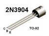
I remember that you used a FET where different pins layputs were on different datasheets. This transistor is much more common than the FET so the pins layout is correct.
I need to measure the DC voltage at the collector right? Maybe I should use 160k and 30k?[/QUOTE]
Yes, measure the collector DC voltage with a 'scope. It should be between 2V and 3V. The transistor should work fine with your 180k and 33k resistors at its base.
Hi,
First of all, I have to say, "HOORAY~"
It is working!!!! Nothing is wrong with the circuit or the connection, tuning makes it to be complicated.
The DC voltage at the mic is 2.7 volts and the DC voltage at the collector of the 1st transistor is 2.8 volts.
I found that it is very very very very very difficult to tune the trimmer cap.
I used FM radio of my MP3 player and Fm radio of my friend's mobile phone, at 96.4MHz, it sounds very very poor at around 10 feet. Even when the transmitter and receivers are in side by side, the sound quality is still poor and much noisy.
It's really hard to tune the trimmer cap. I think maybe 0.1 degree can affect the transmission. Besides, I've bought a long screw driver which is said that used to tune a trimmer cap, but the front part is made from a small piece of metal (I think it is metal). When I used it for tuning, I can hear someting when the screw driver is touching the trimmer cap, when it is removed, the sound is different. Now I'm using my student card to tune, better and reliable
Now I'm having problem with the sound quality.. .. Anyway, thanks audioguru for willing to help..
My FM transmitter overloads my cheap FM radios when it is close. Then spurious signals appear all over the dial and most are very distorted because they are just overload signals, not the correct signal frequency. My Sony Walkman radio has a Local-Distant switch that reduces the overloading when it is switched to Local.
Try reducing the length of the transmitter's and radio's antennas and space them apart to avoid overload, then only a single correct frequency will be on the radio's dial.
The mic preamp is very sensitive and will cause acoustical feedback howling if the radio is in the same room as the transmitter, and severe distortion if you speak too loud or too close to the mic. It picks up voices at a distance of 2m to 3m.
Try reducing the length of the transmitter's and radio's antennas and space them apart to avoid overload, then only a single correct frequency will be on the radio's dial.
The antenna of the transmitter is around 10cm, vertical. I thought the distance of transmission is reduced if the length of the antenna is reduced?
The mic preamp is very sensitive and will cause acoustical feedback howling if the radio is in the same room as the transmitter, and severe distortion if you speak too loud or too close to the mic. It picks up voices at a distance of 2m to 3m.
This site uses cookies to help personalise content, tailor your experience and to keep you logged in if you register.
By continuing to use this site, you are consenting to our use of cookies.

 I was wondering about your transmitter. Do you ever have a problem with over deviation? You know that sounds like crap in the receiver or do you just have a real low audio level? Sorry dude....could not resist that one...lol.