Continue to Site

Welcome to our site!

Electro Tech is an online community (with over 170,000 members) who enjoy talking about and building electronic circuits, projects and gadgets. To participate you need to register. Registration is free. Click here to register now.

  • Welcome to our site! Electro Tech is an online community (with over 170,000 members) who enjoy talking about and building electronic circuits, projects and gadgets. To participate you need to register. Registration is free. Click here to register now.

Fly Zapper Racket - Shock Device - Replacement Components

Status
Not open for further replies.

Scalamoosh

New Member
I managed to acquire a shocking device from a friend, which originally was a fly zapping racket.

I am unsure exactly what modifications he has made to it, but i'm guessing it was just changing the shocking grid for two prongs.

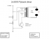
when I got it off him, the circuit looked something like this:

**broken link removed**

i then removed the 22M resistor from the capacitor side of the circuit to increase the power, keep the cap charged when turned off.

I was then left with:

**broken link removed**

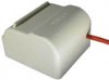
The transformer then got damaged so I decided to replace it, but there was no markings on it and I had no ways of testing it. A friend suggested an audio output transformer. I bought one of these but the new transformer has 5 pins, instead of the original 6.
I also lost a couple of the other components by this time, and I am wanting to re-build it now. the components I have and the circuit I was thinking was:

**broken link removed**

however I don't want to go ahead with building this, just to end up blowing some components. please could someone advise me on what the circuit should look like, and if I need to change some of the components listed..

Thanks in advance!
 
Last edited:
Do not use the 2N2222, it is only good for 500 mA and it will burn out. I reccomend that you use a seperate coil for the feedback like in this schematic.
 

Attachments

  • resonant flyback .png
    resonant flyback .png
    53.4 KB · Views: 8,230
Thank you for your response, however i do not understand the whole coil part. this may seem really stupid but it is just something i have never used or needed to use.

how would i go implementing the coil on the diagram?

thanks again
 
This is a flyback driver schematic, so, use a flyback transformer. You can use a small flyback transformer to get the high voltage, I had a small 1000V flyback transformer and I had constructed a similar device using this driver and it worked perfectly. Those small flyback transformers can be found in plasma ball toys.
 

Attachments

  • hvt-01w..jpg
    hvt-01w..jpg
    6.3 KB · Views: 1,266
If you are a little kid then please grow up.
Why don't you make something useful instead of zapping people which might kill a weak person?
 
Audioguru is right, I thought that you just wanted to repair the fly zapper. Do not use this device to shock people. YOU COULD KILL SOMEONE!
 
Last edited:
I understand the dangers in using these devices, and i'm doing it mainly to learn and try to teach myself what works and doesnt work!

back to the advice given, i am not wanting a constant HV over the grid or spark gap. i am wanting to use the generated HV to charge a capacitor which can be discharged later. this is how the device used to work before i damaged the original transformer...
 
The original circuit used a high current transistor and a transformer that produces a very high voltage (thousands of volts).

Your replaced parts are a low current transistor and an audio transformer that steps up the battery voltage to only 20V.
 
could you advise me on which components i need to buy to get the device working as it was, if not improving it please?

the components were not marked in any way so i couldn't get any part numbers or specifications.
 
I don't know where you will find a high voltage transformer. Custom made? It will cost a fortune.
 
so i wouldn't be able to find one of these high voltage transformers in some other device?
i thought with the price of the fly zappers being really cheap, the components must be also really cheap to replace..

thanks for your advice again, but i'm out of my depth when it comes to things like boost converters and flyback transformers... :-/
 
The zapper is made by the millions and in a country where everything is very cheap. The workers are barely paid.
Maybe you can ask in a camera store for the remains of a disposeable camera for you to take its high voltage transformer but its output is "only" 350V.

I have never seen a fly zapper in Canada. Flies are where things are rotting and I don't go there.
 
Ok, thanks for the advice, in comparison what would you estimate the voltage of the original transformer to be?

and if it is not as powerful, would it just take longer to charge, or would it only charge it to 350v?
 
Put that thing into a trash can and purchase a new one.

They are 100 Thai Baht [TBHT], US$ 2.50, not worth repairing them. Don't remove the 22M resistor again. It serves the purpose of protecting from short circuit.

Boncuk
 
hmmm, well i am not wanting to get this thing working again to actually use it, its more of a hobby/practice thing. Buying another one will teach me nothing about the workings of it, or how to fix the problem!

I am going to visit my local component shop tomorrow to buy what is needed, if i could get help from people here that would be great!

basically, i am wanting to create a circuit that will quite quickly charge a 630v capacitor and store that charge until i discharge it, or bridge the connections.
i have quite a small enclosure for the circuit though, so it needs to be as small as possible.
the more power, or the bigger the spark the better. (i understand the dangers, and im not wanting it to shock anyone with)

any help with this would be much appreciated!


also, does anyone have a link for a small circuit that will constantly arc between two points. the amount of power here is not important, i am wanting it purely for the visuals..

thanks again for all your help guys!
 
Status
Not open for further replies.

New Articles From Microcontroller Tips

Back
Top