Electro Tech is an online community (with over 170,000 members) who enjoy talking about and building electronic circuits, projects and gadgets. To participate you need to register. Registration is free. Click here to register now.
Welcome to our site! Electro Tech is an online community (with over 170,000 members) who enjoy talking about and building electronic circuits, projects and gadgets. To participate you need to register. Registration is free. Click here to register now.
As you are running out of time I would keep the calls where they are and do as Gobbledok suggested I.E. put the LCD code after zeroing count in INT_COUNTER.
As you are running out of time I would keep the calls where they are and do as Gobbledok suggested I.E. put the LCD code after zeroing count in INT_COUNTER.
Thanks i just did that and is working fine now really thanks.
something else that it came in my mind just now.after the count=150 and i get the correct heart rate on the LCD the count resets and starts again from zero and continue counting..do i need to somehow stop counting again after the 150 times? and if yes how i can do that?
I did transfer the code in the PIC yesterday and i connected it with the rest of the circuit. when i turn on the power supply of the circuit and place my finger between the optical sensor on the LCD i can see HEART RATE=0 and nothing is changing. or sometimes when i turn the power on, the LCD says HEART RATE=900 or 960 or 280. why you think is that? maybe there is a problem with my main circuit?cause as you told me the code is correct.
Are you able to measure the output of your optical sensor to make sure it is giving an output? Perhaps replaced the optical sensor with a (debounced) switch and see if it works that way.
Are you able to measure the output of your optical sensor to make sure it is giving an output? Perhaps replaced the optical sensor with a (debounced) switch and see if it works that way.
i measured the output of the optical sensor few days ago and i was getting something like that (please see attached). i also attached my circuit with the first on the left is the sensor and current to voltage converter. the second circuit is the amplifiers and filtering and the last on the bottom is the Schmitt Trigger.
Are you able to measure the output of your optical sensor to make sure it is giving an output? Perhaps replaced the optical sensor with a (debounced) switch and see if it works that way.
Are you able to measure the output of your optical sensor to make sure it is giving an output? Perhaps replaced the optical sensor with a (debounced) switch and see if it works that way.
i used just now a debounced switch. and when i turn on the power supply right away the LCD displays Heart Rate=900. when i press the debounce switch for some time after it displays Heart Rate=94 all the time. if i dont press the debounced switch after a while the LCD displays Heart Rate=000
Are you able to measure the output of your optical sensor to make sure it is giving an output? Perhaps replaced the optical sensor with a (debounced) switch and see if it works that way.
Sorry I'm busy at the moment so haven't had a chance to have a proper look at the diagram but the PIC inputs need about 0.25 x VDD for a TTL input and about 0.8 x VDD for a schmitt trigger input.
It's a pity you can't view the output of your optical sensor with an oscilloscope.
Edit: Just saw your other post. Is that line the output of your last op-amp stage or is that the output from your sensor? Edit again: Scratch that, your current buffer should be fine.
Perhaps you need a comparator after the last stage of your signal buffer to square up the signal? Edit again: Scratch that, your current buffer should be fine.
I did test my sensor yesterday but it doesnt seem to be a correct output. No the signal that i posted is not from my sensor.i just ask if it should looke like something like that? i ve used a debounced switch connected to the input of the PIC and as many times i press the switch it actually gives the correct output on the LCD. so i think something is wrong with my circuit or sensor. also i think there is a mistake with code because when i turn on the power supply it appears on the LCD for some seconds Heart Rate=896 and then it restarts and gives the correct output after 10 seconds.
do you know why is that? and if you can find some time to check the circuit that i uploaded here for any wrong connections i will really appreciate it.
I am using IR Emitter (LED55C) and a photodiode (BPW41N). do you think is a good choice or i should change them?
Thanks for your help
Regards
kokos
Does the LED on the output of our final op-amp light up when you have the pulse meter on your finger? That'll tell you (sort of) what the PIC is seeing.
Are you able to see at all what the output of your final op amp stage is doing?
I'd try using a simple comparator circuit instead.
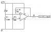
Try this circuit and see if it works.
You will probably have to tweak the values of R1 (for the photodiode) and R2 (hysteresis).
VR1 adjusts the point where the comparator goes high.
Does the LED on the output of our final op-amp light up when you have the pulse meter on your finger? That'll tell you (sort of) what the PIC is seeing.
Are you able to see at all what the output of your final op amp stage is doing?
I'd try using a simple comparator circuit instead.
Try this circuit and see if it works.
You will probably have to tweak the values of R1 (for the photodiode) and R2 (hysteresis).
VR1 adjusts the point where the comparator goes high.
No the LED is flashing the whole time with the same rate even when the sensor is not connected to the circuit. when the sensor is connected the LED flashes much slower than before but the LCD displays numbers which are not real. i think that the LED shouldnt be flashing when the sensor is not connected is that right? but the PIC is actually doing the correct calculations because when i connected it with a debounced switch i can see that is correct.
The checked the output of the final stage with an oscilloscope and is square pulses.what values of R1 and R2 do you recommend for the circuit you just send me? i have 100k, 1M, 2.2M, 10K, and 2.2K and 1K.
The checked the output of the final stage with an oscilloscope and is square pulses.what values of R1 and R2 do you recommend for the circuit you just send me? i have 100k, 1M, 2.2M, 10K, and 2.2K and 1K.
I would try R1 as it is at the moment. If the IR sensor isn't sensitive enough (as it appears to U1), raise the value of R1. R2 is for hysteresis and its value depends on R1. As it is at the moment there is a lot of hysteresis and you can probably raise it even up to 10M.
For the resistors you have at the moment, try 100K for R1 and 2M2 for R2.
Edit: you will have to limit the output of the op amp to 5v so you don't damage your PIC. Probably the best way to do this is to use a rail-to-rail op amp and run the whole circuit of regulated 5v.
Thanks for your help.i will try it and see what i can get
today i bought TSL235R photodiode which it converts the current to frequency and it can be directly connected to PIC. do you think that my code for the PIC will response to the output of TSL235R?
Thanks for your help.i will try it and see what i can get
today i bought TSL235R photodiode which it converts the current to frequency and it can be directly connected to PIC. do you think that my code for the PIC will response to the output of TSL235R?
i ve tested the TSL235R and sometimes it gives the correct output on the LCD but sometimes not. what do you think that i should add more in order to keep the TSL235R? because to rewrite my program will be a bit difficult i think as i dont have access to the flowcode at the moment. or you think that i should use a normal photodiode with a current to voltage converter? TSL235R it is used in medical devices for heart rate monitors or pulse oximeters so i think it is efficient enough.
It's not the efficiency which is the problem... It's the interface. How do you plan on distinguishing between frequencies without rewriting your code? You can't measure the TSL235R the same way you can measure your current photodiode.
I think you're better off sticking with what you have but trying to 'square up' the signal so you get one pulse per heartbeat. The easiest way of doing this is with a comparator. It's hard to know where to set the points or how sensitive it has to be without knowing the output of the sensor when placed on (either side of) the finger. I would try the circuit I posted above. I'd use a 330K for R1 and a (say) 8M2 for R2. Place an LED on the output and adjust VR1 until you (hopefully) get the LED coming on with each heartbeat.
This site uses cookies to help personalise content, tailor your experience and to keep you logged in if you register.
By continuing to use this site, you are consenting to our use of cookies.