Continue to Site

Welcome to our site!

Electro Tech is an online community (with over 170,000 members) who enjoy talking about and building electronic circuits, projects and gadgets. To participate you need to register. Registration is free. Click here to register now.

  • Welcome to our site! Electro Tech is an online community (with over 170,000 members) who enjoy talking about and building electronic circuits, projects and gadgets. To participate you need to register. Registration is free. Click here to register now.

First ROBOT with L293D problem

Status
Not open for further replies.
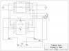
I tried that diode ckt with zener diodes but didn't work , I am trying to figure out whats wrong, hope will find it. I have a spare ATX PC power supply and I have spent already over my budget so I really need to know how to use that, please tell me because soon I'll be out of battery.

Edit:
I just have those zeners and hope that may work because can't afford to buy 8 new diodes right now.

Chris,
They are NOT zener diodes.

Use 1N4001 diodes or equivalent. 1Amp 50Vpiv

Which type of Zener did you try.?
 
I used 1N4148 switching diodes.

hi Chris,
They are signal diodes, not zeners.:)

Can we recap to so that we talking about the same points.

What mains adaptor are you using, volts/amps.? or battery volts/type.

Are the 1000uF and 100nF's on the pcb.?

What are the symptoms/problems you get under what conditions.
Basically whats happening when you run the project.
Saying it dosnt work does not help me understand the problem.

Can you say where you are located.?
 
Last edited:
Hi Eric,
Really sorry about messing up with words, O.K. so this is happening :

After connecting that diode ckt (with 1N 4148) both motors runs very slow and after detecting light on one side ( deviating from black line on one side ) the corresponding motor get reversed ( yet very slow),
While on the other side ( i.e.: with the other motor, while the BOT goes off the line on the other side ) the whole ckt get hang and I have to restart it.

NOTE:

In this attachment I tried to show almost exact places of components, I have it on strip board so the horizontal connection are the strips only and actually it is not that much conjunctive as it looks.

As you can imagine some components actually not required wire connection as their leads are sufficiently long.

Edit: PLEASE CONSIDER 1000uF CAPACITOR IN REVERSE POLARITY. SORRY!:eek:
 

Attachments

  • ROBO 2.jpg
    ROBO 2.jpg
    192.7 KB · Views: 364
Last edited:
hi Chris,
Look at this marked up dwg.

The 7805 requires 100nF caps close to the input and outputs, these caps are required to prevent the7805 from instabilty.

Your schematic does not show the power supply input to the 7805.?

L293 pin9 3,4 Enb is not connected.

The 1N4001 diodes are required.

Did you write the program.?

ericgibbs has much to be proud ofericgibbs has much to be proud ofericgibbs has much to be proud ofericgibbs has much to be proud ofericgibbs has much to be proud ofericgibbs has much to be proud ofericgibbs has much to be proud ofericgibbs has much to be proud ofericgibbs has much to be proud of

Default
Quote:
Originally Posted by c36041254 View Post
I used 1N4148 switching diodes.
hi Chris,
They are signal diodes, not zeners.

Can we recap to so that we talking about the same points.

What mains adaptor are you using, volts/amps.? or battery volts/type.

Are the 1000uF and 100nF's on the pcb.?

What are the symptoms/problems you get under what conditions.
Basically whats happening when you run the project.
Saying it dosnt work does not help me understand the problem.

Can you say where you are located.?
 

Attachments

  • bot1.gif
    bot1.gif
    31 KB · Views: 375
Last edited:
Hi Eric !
First, do you mean to say that pin 3 and 4 are not connected in schematic ?, well I made that sch. in just few minutes so please excuse me for that, in actual ckt they are well connected where they should be.
I am using the typical 9V battery ( that adapter got some problem, I mentioned in some earlier post ).And yes I wrote the program which is in much much basic form:eek:.


Code:
list p=16f628A
		#include<p16f628.inc>
		__CONFIG  _MCLRE_ON & _CP_OFF & _WDT_OFF & _INTRC_OSC_NOCLKOUT
		ERRORLEVEL   -302
		cblock	0x20
			temp 
			temp_s      
  		endc
;******************************************************************
	org 0x00
	goto main
;***********************************INTERRUPT LOOP*****************
	org 0X04
inter:
		movwf 	temp
		swapf 	STATUS,w
		clrf  	STATUS
		movwf	temp_s
		btfsc	PORTB,0x00
		goto	loop1
loop2:
		movlw b'00000101'
		movwf	PORTA
		btfsc	PORTB,0x05
		goto	loop2
		goto	loop_x
		
loop1:		
		movlw 	b'10001000'
		movwf 	PORTA
		btfsc 	PORTB,0x00
		goto  	loop1
loop_x
		bcf   	INTCON,0x01
		bcf	  	INTCON,0x00
		swapf 	temp_s,w
		movwf 	STATUS
		swapf 	temp,w
		retfie

main:
		bsf		INTCON,0x07			;Globel interrupt enable(we are using interr.)
		bsf 	INTCON,0x04	
		bsf		INTCON,0x03			;RB4-RB7 interrupt on change is enabled/ in other words these pins will also work as
								;interrupts and interrupt will occur every time any of these pin changes state
								; i.e.:HIGH to LOW or LOW to HIGH, we can not set it to be on eather one state change  		
		bcf 	INTCON, 0x01		
		bcf		INTCON,	0x00			;Clear RB4-RB7 interrupt flag so, that another interr. can occur.

;**********************************SET UP THE PORTS *****************
		bsf		STATUS,RP0			;switch to BANK 1
		movlw 	b'00100001'	
		movwf 	TRISB				;set RB6 & RB5 as input
		movlw	b'00000000'
		movwf 	TRISA				;setPORT A all output
		bcf 	STATUS,RP0			;back to BANK  0
		movlw 	0x07				;turn comparators off, so HIGH will be simple
								; HIGH rather than +5V (compared to supply) so with the LOW
		movwf 	CMCON				

Loop:

		movlw 	b'00001001'		
		movwf 	PORTA				;set pin 0 of port a HIGH
		goto 	Loop
		END

PLEASE DON'T TELL ME TO CHANGE THE PROGRAM AS I HAVE MADE THE HARDWARE.
Just to verify 100nF = 108pF. Isn't it ?

FYI: I live in India.
 
Last edited:
hi Chris,

Just to verify 100nF = 108pF

100nF is sometimes written a 0.1µF

I try your program in my Sim.
 
Last edited:
I don't get that !!:confused::confused:

100nF = 108pF or not? Because I always been taking 0.1uF = 104pF .
Oh ! I'm confused in such a basic thing.:confused:
 
I don't get that !!:confused::confused:

100nF = 108pF or not? Because I always been taking 0.1uF = 104pF .
Oh ! I'm confused in such a basic thing.:confused:

Chris,
10^-3 = milli, 10^-6 = 1 micro, 10^-9 = 1 nano, 10^-12 = pico

I would suggest you use the conventional 'break points' in '000' steps.

Anyway look at this program run result.

your code.
Code:
movlw 	b'00100001'
movwf 	TRISB		;set RB6 & RB5 as input

Look at the direction of the PORTB pins 5 and 6 [ in the image]

BTW: the 'T' means its an Input..

EDIT:
Some links to explain the cap coding.
http://www.kpsec.freeuk.com/components/capac.htm
**broken link removed**
http://www.pc-control.co.uk/capacitor_codes.htm
**broken link removed**
 

Attachments

  • esp02 Sep. 01.gif
    esp02 Sep. 01.gif
    9.3 KB · Views: 302
Last edited:
Thanks for those links ! Do you mean to say that I should not have kept pin RB 5 as input when I'm not using it ? Please be simple in language because this is my first ever MCU project.
 
Chris, I am not sure from the posts if you have been able to use a better 12 V supply. The PC ATX supply you mention ought to have a 12 V line as well.

Trust me the adaptor IS the issue. I made a robot using tape deck motors about 5 yrs back. I had no gearboxes on the motors too. It was SO frustrating to see the robot barely move. The 12 V from the computer worked wonders.

Where in India are you ?

Also try not to use L293 chip in your next project. I use a chip that is 1/3rd its cost and provides 1.6 A current. Its BA 6209 and is just Rs 30. Theres also BA6222 which gives 2.2 A current and costs Rs 50.
 
Hi Pradeep !
I know that ATX supply has 12V and I really need it to work as my adapter got some problem and I have used six of those 9V batteries and can't afford to buy a new one. The problem is that that ATX has 12V , 16A how can I make it 1A? Please tell me. I also blown the fuse of multimeter for that 16A :eek:
FYI : Gujarat
 
Last edited:
Hi Pradeep !
I know that ATX supply has 12V and I really need it to work as my adapter got some problem and I have used six of those 9V batteries and can't afford to buy a new one. The problem is that that ATX has 12V , 16A how can I make it 1A? Please tell me.
FYI : Gujarat

Chris,
The project will only draw as much current as it requires from the 12V 12Amp source.
If your project requires 1A, thats all it will draw from the 12A.
 
Thanks for those links ! Do you mean to say that I should not have kept pin RB 5 as input when I'm not using it ? Please be simple in language because this is my first ever MCU project.

You say in the program comments that RB5,6 are Interrupt inputs, but RB6 is set as an output, so an Intr on this pin will never be detected
 
Hi Pradeep !
I know that ATX supply has 12V and I really need it to work as my adapter got some problem and I have used six of those 9V batteries and can't afford to buy a new one. The problem is that that ATX has 12V , 16A how can I make it 1A? Please tell me. I also blown the fuse of multimeter for that 16A :eek:
FYI : Gujarat


Hi again Chris, as Eric points out dont worry about the amperage of teh supply. Its only the limit to which your robot can draw from it not the minimum that the power supply will push into the robot.

On the blown up fuse, I think you connected the multimeter directly to the power supply to measure its current. You should never do that. You probably only need to measure the current drawn by your robot. for that you need to put the multimeter in series with the robot and power supply.
With poor batteries, the robot will not be able to draw enough current so the multimeter might show a lower than correct reading.
 
Hi Eric !
If I have such a big debacle then why it runs with LEDs connected directly to MCU ?
Though I will correct the mistake I'm just curious to know that so long why it worked.

EDIT:
I JUST USED THE ATX AND KNOW WHAT I SOW SMOKE:eek::eek::(:(:(
THOUGH I CHECKED MCU IT IS OK WONDERING THAT L293D IS OK OR NOT IT WAS HOT NOT LIKE IRON BUT STILL QUITE HOT!!!!!!!!!!!

EDIT :
Is there any way to test L293D ?
 
Last edited:
Hmmm Heat is not good. Probably there is a short circuit or the motors had too much too much load on them. If the L293 gets hot even with the motors free to rotate or motors unplugged altogether then problem is elsewhere.
 
Hi Pradeep,
Luckily both MCU and L293D are O.K. When this happen none motor was connected. I have used preset 100K pot with LDRs to tune the response of LDR ( kindly see my ckt in some previous posts ) and they are always vulnerable to such current disasters though they are also working fine........... Can the 1000uF cap burn out when such thing happen because the capacitor is an old used one.
Is there any problem with using ATX supply ?
 
Last edited:
Hi Eric !
If I have such a big debacle then why it runs with LEDs connected directly to MCU ?
Though I will correct the mistake I'm just curious to know that so long why it worked.

EDIT:
I JUST USED THE ATX AND KNOW WHAT I SOW SMOKE:eek::eek::(:(:(
THOUGH I CHECKED MCU IT IS OK WONDERING THAT L293D IS OK OR NOT IT WAS HOT NOT LIKE IRON BUT STILL QUITE HOT!!!!!!!!!!!

EDIT :
Is there any way to test L293D ?

Hi Chris,
I did advise against connection a PC's psu.!
Hi Chris,
I wouldnt recommend connecting the motor to the PC internal supply lines.

I will check the rest of your PIC/L293 connections and look futher into your program.

IF the L293 is suspect disconnect it from the PIC and drive it with simple switches in order to check it out
You have obviously got something wired incorrectly or not cut out a copper track on the stripboard.
 
Hi Eric,
I should have taken your advice seriously anyway, The ckt seems safe so far.I will try those 1N4001, and still wonder that do I actually need to change the code you suggest while the ckt works fine digitally and even with motor (I have written the program 5 months ago and almost forget the logic or at least most of it and now I just have 6 days to complete the project so don't want to mess with the software part ), the only problem is of hanging when motors are rotating fast and any of the LDR detects light. If I slow down the motors then they work fine I mean completely fine but slow motors can not carry the load of robot.
 
Last edited:
Status
Not open for further replies.

Latest threads

Back
Top