Electro Tech is an online community (with over 170,000 members) who enjoy talking about and building electronic circuits, projects and gadgets. To participate you need to register. Registration is free. Click here to register now.
Welcome to our site! Electro Tech is an online community (with over 170,000 members) who enjoy talking about and building electronic circuits, projects and gadgets. To participate you need to register. Registration is free. Click here to register now.
"ideal" PWM frequency is about one tenth the time constant of L/R, where L is the inductance of the motor, and R is the winding resistance. so for a motor inductance of 100mH and a DC resistance of 10 ohms, L/R=0.001 sec. 0.001x0.1=0.0001, or inverting, we get 10khz.
"ideal" PWM frequency is about one tenth the time constant of L/R, where L is the inductance of the motor, and R is the winding resistance. so for a motor inductance of 100mH and a DC resistance of 10 ohms, L/R=0.001 sec. 0.001x0.1=0.0001, or inverting, we get 10khz.
Here's the motor I'm dealing with, **broken link removed** , got any recommendations of how to calculate the inductance?
I guess my 100 hz PWM may be running kind of slow. Where did you find your info?
Thanks
Kinarfi
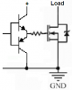
The diode across an inductor that clamps the voltage spike produced must conduct the current that the inductor was passing. If the motor instantaneously reverses then the current might be 200A! Your low power rectifier bridge was useless.
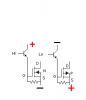
A complementary pair of emitter-followers can quickly turn a Mosfet on and off.
EDIT: Maybe the peak current rating of your rectifier bridge was good.
The diode across an inductor that clamps the voltage spike produced must conduct the current that the inductor was passing. If the motor instantaneously reverses then the current might be 200A! Your low power rectifier bridge was useless.
A complementary pair of emitter-followers can quickly turn a Mosfet on and off.
EDIT: Maybe the peak current rating of your rectifier bridge was good.
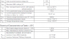
Here's the specs on my bridge rectifier, being as it's only active for a split second, the 170 rating should suffice and the motor can't be "instantaneously" reversed, it has to go from forward to zero to reverse and zero is dynamic braking and I plan to put a 50 amp transducer in the works to turn all H bridge FETs off simultaneously. I'll look into your drawing.
the time constant "rule" is a general "rule of thumb" used in the industry. it's not fixed in stone, but it's used as a baseline for designing PWM drivers for motors. going lower in frequency generates audible noise from the motor. going higher in frequency is ok. the L/R time constant smooths out the current in the motor windings.
Audioguru posted a schematic on post #44.
Don't forget that the resistor connected to the MOSFET's gate is a low value, from 10 ohms to 47 ohms.
Unclejed.
Let's not forget that even running at ultrassonic frequencies, the motor magnets histeresis tends to respond to it and, maybe, you are going to hear a hiss.
Some information I came up with about the motor, at:
6.78 amp = 7.22 v \
6.57 amp = 7.11 v > These were from my power supply with current limit (7 amp max)
6.00 amp = 4.39 v /
Other averaged over time readings
15.08 v/ 6.50 amp cw 15.13 v/ 5.86 amp ccw from my more powerful power supply. Just swapped the leads at the power supply terminals.
Fluke 87 ohms measurement across the leads after pushing the delta button. .1 ohms.
Tomorrow, I plan to put a capacitor in series with the motor leads and apply a square wave and look at it with my oscilloscope. And the try to figure out it's inductance.
Any one have any suggestions.
Thanks,
Kinarfi
use a sine wave and look for a null across the signal source, that's the series resonant frequency. the square wave will just serve to give confusing results because of the harmonic content
use a sine wave and look for a null across the signal source, that's the series resonant frequency. the square wave will just serve to give confusing results because of the harmonic content
It's been a long time since I worked with resonance, so correct me if I'm wrong, please. Parallel resonance has a high input impedance, very low current and series resonance looks like a short, current limited by the resistance, so when you say look for a null, it would have the a peak voltage across the cap, well above the supply voltage.and freq is = 1/2Pi √(F L).
Thanks for the input, tips.
Kinarfi
If you have a scope with dual inputs, the waveform at resonance across the capacitor and inductor will be out of phase 180 deg as they cancel to form your low impedance "short".
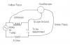
Don't have a variable frequency sine wave generator so here's what I did and it sorta worked, I gathered up every cap I had, got a 120 to 9 wallrat, took the diodes out, hooked one side to 5 ohms 50 watts resistor, other side to a motor lead, resistor to a strip of metal other motor lead to another strip of metal, both L shaped and started laying capacitors across the metal strips. After I got all of my caps in the circuit and saved the trace, I started to measure the combined capacitance and since I hadn't paid any attention to polarization of the caps, it would measure. It was fun though, even if it was a waste of time. Guess I'll build a sine wave generator. Oh yea, Green trace is caps, yellow motor.
Kinarfi
as i said earlier, the time constant method of selecting the PWM frequency is a "rule of thumb". the PWM frequency doesn't HAVE to be selected to have a period of 1/10 the time constant of the motor. the frequency can be higher. the motor windings are averaging the current. i only mentioned it because the OP mentioned 100hz, and that souned like a very low frequency for any motor. start by trying a PWM frequency of maybe 5khz. if the current has a lot of ripple in it at that frequency, go higher, like 10 or 15khz. with a 1 ohm or 0.1 ohm resistor you can monitor the current as a voltage, and feed that voltage into your oscope and see the waveform of the current.
One thought about the winding resistance, according to my fluke 87, the resistance is .1 ohms. Being as it was measured with DC. It is still the series R of the inductor, correct? I say yes.
UncleJed, If I get the exact, correct, Ideal PWM Freq. What should I expect to see for current/ voltage across my external 5 ohm resistor?
I plan to build an sine wave generator today.
Thanks
Kinarfi
This site uses cookies to help personalise content, tailor your experience and to keep you logged in if you register.
By continuing to use this site, you are consenting to our use of cookies.

 and it sorta worked, I gathered up every cap I had, got a 120 to 9 wallrat, took the diodes out, hooked one side to 5 ohms 50 watts resistor, other side to a motor lead, resistor to a strip of metal other motor lead to another strip of metal, both L shaped and started laying capacitors across the metal strips. After I got all of my caps in the circuit and saved the trace, I started to measure the combined capacitance and since I hadn't paid any attention to polarization of the caps, it would measure. It was fun though, even if it was a waste of time. Guess I'll build a sine wave generator. Oh yea, Green trace is caps, yellow motor.