Continue to Site

Welcome to our site!

Electro Tech is an online community (with over 170,000 members) who enjoy talking about and building electronic circuits, projects and gadgets. To participate you need to register. Registration is free. Click here to register now.

  • Welcome to our site! Electro Tech is an online community (with over 170,000 members) who enjoy talking about and building electronic circuits, projects and gadgets. To participate you need to register. Registration is free. Click here to register now.

FC-130: pimping the Tamiya gearbox?

Status
Not open for further replies.
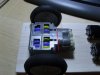
Right, my gearbox arrived today. A few observations;
It's a very fast gearbox, I've built it in the lowest ratio configuration. Without PWM this will be more than sufficient. PWM would allow the next ratio to be used, I think the top two will be useless for robotics.
The gearbox is a strong unit, so it should be able to take a more powerful motor.
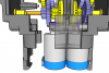
Now the good bit, if you were to remove everything to the left of the red line in my attachment you would be left with a flat bulkhead with holes in it. This would be easy to adapt to take a larger motor (with bracket and suitable gear).
Having said this, the gearbox and motor combo is already impressively fast and powerful.
 

Attachments

  • 1024x768-robot.JPG
    1024x768-robot.JPG
    430.5 KB · Views: 600
Problem might be the motors are side by side, only a slight space exists between them. A larger diameter motor won't work.
 

Attachments

  • MongooseGearbox.png
    MongooseGearbox.png
    86.8 KB · Views: 506
I think if you moved the spur gear to the middle of it's shaft, you could fit slightly larger motors. Or you could use the single motor version, or just use a larger motor and different gearbox (probably the best option!)
 
Those little gearboxes have plenty of torque at 114:1 or higher, what sort of load are you trying to move.
The little brass bearing won't hold out for big loads, you'd realistically need ball bearings.
 
It's hank who wants to mod them, to take a higher voltage motor from what I can tell. I just thought it was fun to have a nosy at the gearboxes to see what could be done!
 
b.r.e. said:
The little brass bearing won't hold out for big loads, you'd realistically need ball bearings.
I'd thought about that for the universal gearbox, which has up to about 700:1 gear ratio. Observing the small robot arm models they have at the local community college, I noticed that the servo-driven joints have additional structure axles. What I mean is, the servo horn is connected to the joint, but the design allows for radial movement of the joined parts by the servo, but there is no force perpendicular to the servo shaft on the servo shaft. Instead, there's another part that takes the perpendicular-force load. I can remember how that did that on the opposite end of the servo horn, but I'm a little fuzzy at how they went about it at the business end - I'd have to see it again. Definitely a bushing not a bearing solution, but then they were small robots made of fairly robust metal (aluminum?).
 
Last edited:
Status
Not open for further replies.

Latest threads

Back
Top