Continue to Site

Welcome to our site!

Electro Tech is an online community (with over 170,000 members) who enjoy talking about and building electronic circuits, projects and gadgets. To participate you need to register. Registration is free. Click here to register now.

  • Welcome to our site! Electro Tech is an online community (with over 170,000 members) who enjoy talking about and building electronic circuits, projects and gadgets. To participate you need to register. Registration is free. Click here to register now.

Farnell E30/1 power supply, is it dual rail?

Status
Not open for further replies.

RoboWanabe

Member
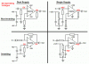
Hi I have a Farnell E30/1 power supply with a -V rail, a +V rail and a GND rail.

I was under the impression that if i set the voltage on the power supply to 18v and then measure between GND and -V i would get -9V and between GND and +V i would get +9V. But when i measure the GND rail seems to be all over the place and im not getting a clean voltage out.

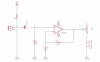
Please somebody help me i need to power my Op-amp circuit with a negative rail and positive rail? would like to test with my power supply.

Also does anybody know how to create a dual rail supply using batteries instead?

Thanks in advance

Red
 
I've no idea if it's a dual-rail supply or not - but there's nothing there to make me think so.

The ground is just that, and not connected to the PSU - it's so you can ground either of the rails if you wish (or leave them isolated).

For a battery dual supply, simply use two batteries - connected +ve of one to -ve of the other.
 
Thanks for the reply Nigel :)

I'll try that with the batteries. is there no way i can simulate it with my power supply? I've tryed using a voltage divider to half the voltagr and then use that as a gnd refrence but i ended up blowing my chip :O i've blown 2 now lol.

Im trying to use a NE5532P to amplify a microphone signal.

Red
 
**broken link removed**
This is not a dual rail supply. From the picture, the supply is either 0-15V/1A or 0-30V/0.5A...switch selected. The + and - output is isolated from ground. The green terminal is ground, so either the + or the -terminal can be jumpered for ground referencing.

Ken
 
Hi KM

So what would be the use in that? why wouldun they just give us a midpoint to use as ground refrence? or is that absolute ground relative to the earth? sorry if these are noob questions lol

Red
 
Ground on a circuit is simply a 0V reference voltage that might be or might not be connected to an earth ground.
Please post your original circuit that has the plus and minus supply then show what you did to try making it work with a single positive supply.

A preamp that uses a plus and minus supply is easily modified to use only a single positive supply. Instead of its (+) input connected to ground through a resistor it is connected to half the supply voltage with a voltage divider which is fed through a resistor. Also the input, output and feedback resistor to ground need to have series coupling capacitors like this:
 

Attachments

  • opamps.gif
    opamps.gif
    16.8 KB · Views: 471
Thanks for the reply Nigel :)

I'll try that with the batteries. is there no way i can simulate it with my power supply? I've tryed using a voltage divider to half the voltagr and then use that as a gnd refrence but i ended up blowing my chip :O i've blown 2 now lol.

Im trying to use a NE5532P to amplify a microphone signal.

If you've blown the chip you've done something seriously wrong - so badly wrong I can't even imagine what you've done?.

Perhaps you could post the exact circuit you used?.

However, for a microphone preamp a simple voltage divider of two resistors and one capacitor is all you need to use a single supply, as long as you connect everything correctly.
 
Thanks audio guru.

I've attached the circuit I'm following. For the supply I just used the power supply mentioned, at first using the ground (which turned out to be the wrong ground) and then using 2*100k resistors with the supply set to 18v, this should give me a midway refrence point to use as ground for the op-amp???. Doing it both these ways, I seem to get odd results and then nothing.. like they've blown. I'm going to try using to nine volt batteries the way Nigel mentioned and see if this works.

Nigel maybe i haven't blown, them i still went and brought another 2 and if i can get one working ill try them again :). Im currently waiting for my oscilliscop to warm up lol because i'm in the garage and its Freeeezing!! it seems to take a while to fully come on. I'm using a Philips PM3215 oscilliscope.

How warm is every one elses electronic hobby rooms just out of interest? I get worried my equipment is going to brake, in fact that is what i was thinking about my ground refrence of the power supply jumping all over the place.. Ill get there one day :)
 

Attachments

  • circuit 1.png
    circuit 1.png
    62.9 KB · Views: 250
well i cant believe it, it turned out to be a broken jumper lead lol that teaches you not to buy cheap ones from Farnell. All op-amps are alive and circuit is working beautifully

Thanks for your help guys
 
Thanks :)

When I look at my output, the signal drops by about 1v below ground? and when i measure the voltage at gnd to -V i get -9.48V and when i measure the +V i get 9.17v. Is the drop to do with the voltage being un-even?.

How can i stabilize it? do you have any suggestions on improving the circuit im using

Thanks for your help

red
 
Thanks :)

When I look at my output, the signal drops by about 1v below ground? and when i measure the voltage at gnd to -V i get -9.48V and when i measure the +V i get 9.17v. Is the drop to do with the voltage being un-even?.

How can i stabilize it? do you have any suggestions on improving the circuit im using

What that the partial circuit you posed earlier?, post the complete circuit exactly as you've wired it.
 
You posted the schematic of a very low power LM324 opamp trying to drive a speaker? An LM324 is not a power amplifier, an 8 ohm speaker needs a peak current of about 1000mA from a power amplifier when it has dual 9V supply but the minimum output current from an LM324 is only 10mA. The datasheet for the LM324 shows a minimum load of 2000 ohms. It is too noisy (hiss) for a microphone preamp, has trouble with frequencies above only 2000Hz and it has crossover distortion so it should not be used for audio.
Why did you replace the pretty good NE5532 opamp with the lousy old LM324 opamp? Why don't you have a power amplifier to drive the speaker with the preamp driving the power amplifier?

You should NEVER connect a volume control in series with a speaker. The volume control should be a signal voltage divider at the input of the power amplifier. The speaker needs to use the extremely low output impedance of the power amplifier (0.04 ohms or less) to damp its resonances so it does not sound boomy.

The datasheet for the LM324 shows a maximum input offset voltage of 9mV and a maximum input bias current of 0.5uA. Your opamp has a DC gain of 101 times so its average output could be anywhere from-6V to +6V. If the 1k resistor has a series capacitor to ground causing the DC gain to be 1 then the average output voltage will be very close to 0V.
 
Nigel
Sorry I'm following a tutorial on you-tube and i screen captured from there. I'm working in my garage and i don't have any good schematic software to show you my circuit. I'm installing LTSpice now, I've never used it but will give it ago.

Audio Guru

Thanks :) I am still using the NE5532 i was just showing the circuit i'm working from. Do you have an alternative for the NE5532 i can work from instead?
The plan was to just power a pair of headphones so i didn't think i needed to use a power amplifier. So the input voltage control should be just after the capacitor on the input circuit?

Thanks for your help :)
 
Hi Guys. I've remade the circuit I'm using with Lt-spice. This is how I've wired the circuit, you have the power rails and grand rail generated by the circuit to the right. I couldn't find the NE5532 op-amp so I just chose the op-27.

Any design improvements?

Thanks
 

Attachments

  • Opamp circuit.png
    Opamp circuit.png
    15.1 KB · Views: 211
Again, your preamp amplifies its own DC offset voltage and offset current.
The datasheet for the opamp tells everything when you add a little simple arithmetic:
1) The max input offset voltage is 5mV so the gain of 101 times makes the output anywhere between +0.5V to -0.5V and the input bias current is 0.8uA max which makes the output anywhere from -8V to +8V (saturated). This DC prevents the amplifier from working and might destroy headphones. It is fixed by adding a properly calculated capacitor in series with R2 to ground.
2) The NE5532 datasheet shows a minimum load of 600 ohms. Your headphones might be 8 ohms or 32 ohms per ear so they will have a distorted low level.
3) Like most audio opamps, the NE5532 operates up to radio frequencies so it will probably oscillate at a high frequency causing severe distortion when a headphones cable connects to its output. It can be fixed by adding a 100 ohm resistor in series with its output which will further reduce the level into low impedance headphones.

Why do you use two 9V batteries? An NE5532 works perfectly into a minimum 600 ohm load with a single 9V battery when connected as I showed.
 
Sorry I hadn't had time to implement your design yet, I've also been messing around with a ICL7660 voltage converter lol I'm still just trying to learn all the basic principles of powering a circuit so I thought id try different ways, ill give your idea ago tomorrow. Are there any benefits for using a single supply or two ? except getting to use one battery.

I'm struggling getting my head around connecting a load to a circuit like this and how much current etc it will draw from the op-amp, and also how much current is going into the inputs etc?

I think im going to have tho get the books out again :) unfortunately I've spent the last year and a half as a software engineer and kind of forgot alot of electronics degree :(

Thanks for the help audio guru
 
The most important spec you have not told us is the impedance of your headphones and if you will connect its two earphones in parallel.
If they are the normal 32 ohms now and are in parallel then the load on the opamp is 16 ohms, much lower than the minimum of 600 ohms.
The datasheet of the NE5532 shows that the minimum peak output current is only 10mA, then the RMS current will be 7.1mA.
The power into each earphone is 7.1mA squared x 32 ohms= 1.6mW which is almost nothing. The signal level at the headphones will be only 0.23V peak which is also almost nothing. Adding a 100 ohm resistor in series to prevent oscillation will not make much difference.

The above calculation is with an NE5532 opamp having the weakest spec's for the loudest parts of music and speech. Average levels will be about 1/5th of them. An NE5532 opamp with the strongest spec's will produce output power that is 36 times higher.

If you design your mic preamp the way I showed with a single 9V battery powering it then it can drive a little power amplifier like an LM386 also powered by the battery.
When the 9V battery drops to 6V and you use two 32 ohm earphones in parallel so the load is 16 ohms then the output power will be 125mW which makes the loudest parts nice and loud and the average power will still be pretty loud.
If the battery is new at 9V then the loudest output power will damage your hearing so a resistor should be added in series with the headphones to limit their power.
 
I was just going to grab any pair of headphones and attach them to the output :(. I'm not sure how to find out the impedance of the head phones, is there anyway i can test this at home?

At the moment im not even using head phones i just have my oscilloscope attached directly to the output. Could the fact that i have no minimum 600Ohm load be causing my signal to drop to -1v? or is this todo with there being a offset DC voltage on the Input?
Don't worry i'm going to spend the rest of today looking at my books :)
 
Status
Not open for further replies.

New Articles From Microcontroller Tips

Back
Top