Continue to Site

Welcome to our site!

Electro Tech is an online community (with over 170,000 members) who enjoy talking about and building electronic circuits, projects and gadgets. To participate you need to register. Registration is free. Click here to register now.

  • Welcome to our site! Electro Tech is an online community (with over 170,000 members) who enjoy talking about and building electronic circuits, projects and gadgets. To participate you need to register. Registration is free. Click here to register now.

Expert analysis welcomed on my Audio amplifier circuit

Status
Not open for further replies.

normanneil01

New Member
Hi everyone, I'm fairly new to electronics and have built a amplifier circuit with tone control and VU led meter.

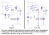
IC1 is a LM741 op amp, IC2 a LM386 power amp and IC3 a LM3915 dot/bar display chip.

I combined the LM386 with the LM3915 and added the tone control circuit from a common circuit found all over the internet. I have built the prototype and everything seems to work fine. I get distortin at high levels but I think that might just be the poor performance of the 386 rather than any build problems. As far as 'testing' goes I'm a total amateur so don't know what I should be trying to work out. I know that the gain of the amplifier is 20 but I don't know the impact the 741 circuit will/should have on that.

Any expert help and/or advice would be great.

I have attached the circuit diagram.
 

Attachments

  • Circuit picture.jpg
    Circuit picture.jpg
    131.9 KB · Views: 456
The 741 is an old part. There are better "audio" parts. There will be comment from Canada in a little bit about the LM741.

The LM3915 is driven directly by the power amp. (through C11) I need to look at the data sheet. I don't think it is save to drive it to -4 volts like you are doing. We need to think on that a little.
 
there is a couple of mistakes on component values that I didn't change. C2 - 47nF, C3 - 22nF, C4+C5 - 4.7nF and R11 - 4.7k
 
I originally built the circuit using the LF351 but the tone controls didn't work. The output was a little clearer but quieter too. I simply swapped with the LM741 and everything worked fine. Maybe a dodgy chip, I don't know, but for the purpose of this exercise I am happy to use the LM741.
 
Your schematic is too small for me to see any of its text. Please post a schematic that will be full size on my screen. Don't save it or post it as a fuzzy JPG file type. Make it a very clear PNG file type instead.

The lousy old 741 opamp was designed 46 years ago to use ONLY a 30V total supply. Some do not work if their total supply is less than 12V. It is too noisy for audio (it has lots of hiss) and it cannot produce frequencies above only 9kHz at a high level (most opamps today produce full output at 100kHz or higher very well).

The LM386 cannot use a supply voltage high enough for good sound. It gets too hot if it plays loudly when its supply is higher than 9V. with a 9V supply its output has fairly low distortion at only 0.45W or less which is as loud as a cheap clock radio. With a 6V supply its max output is a whopping 0.2W into 8 ohms (flea power).
 
Added a better shot of the circuit diagram. Whilst I appreciate that my choice of IC's may not be the best, they are what I'm working with. I'm not looking to blow Michael J Fox back to 1985, I only want to demonstrate an audio signal that I can control with the 3 band tone and have an output meter. At the moment, and as far as I can see, this appears to work.

I only need it to perform and function as it should. It is based on a design idea for a small, portable audio amplifier that, for example, could be used to plug an ipod/mp3 player into or as a portable speaker for a laptop. I have added a drawing of a possible unit.

I promise you, if I succeed here I will move onto more powerful chips and op amps.
 

Attachments

  • circuitpicture 3.png
    circuitpicture 3.png
    28.9 KB · Views: 367
  • amplifier drawing.jpg
    amplifier drawing.jpg
    91.4 KB · Views: 279
Thank-you for the improved and larger schematic. Your output is 0.45W at clipping when the 9V battery is new which is not loud. If the tone controls are set to boost anything then the average level will be much less if horrible clipping distortion is to be avoided.

The LM3915 has R13 and R14 setting the maximum output to light up to the 6th LED but the 7th, 8th, 9th and 10th LEDs will always be dark. If R14 is changed to 3.3k and R14 is changed to 4.7k then all 10 LEDs will light when the loudness is at maximum and the battery is new. The brightness of the LEDs will remain almost the same as now.

You have pin9 on the LM3915 set for BAR mode which lights all the LEDs at maximum input level which will quickly kill a little 9V battery.

I made a little amplifier speaker system for the beach a long time ago. My woofer was 4" (102mm) and my stereo satellite speakers were 3" each. The woofer amplifier produced 3.5W which is almost 8 times more than yours. It permanently had some bass boost. The satellite amplifiers were 0.9W each. It sounded much better than any ghetto blaster that could be purchased in those days.
 
Hi normo,
To me it sounds like your circuit works just fine.
I note the tone control system is a typical design thats been used for a VERY long time. It is a frequency selective feedback loop around IC1.
You need to remember that these controls give at least 10 decibels of boost or cut. At bass frequencies, 10 dB of boost increases the power output from say 0.1 watt to 1 watt. So it is very easy with bass boost controls to seriously overload the amplifier. I am sure this is what you are complaining about.
The answer of course is to have amplifiers that produce much higher output power. The normal listening level of say 1 watt then goes to 10 watt and if the amp and speakers can handle this power level then it is easy to listen to. The most common reason for people complaining about 'it's too loud' is because of distortion of the output signal due to clipping and overloading.
In my house I have a pair of Goodmans coaxial loudspeakers and their sensitivity is around 98dB per watt in the living room. I only need a 20 watt amp running typically around 1 to 2 watt to fill the house with sound.
Plenty of loudspeakers have sensitivity factors of less than 90 dB per watt and for these, you need amplifiers of 50 to 100 watt rating to produce good clean sound at high sound pressure levels.
I know this is a bit off your post, but its all about getting enough sound pressure to satisfy your needs. Your amp would probably be best used with headphones but be careful you dont blow up your hearing.
 
I appreciate you all taking the time to look at it for me. I had already tinkered with R13 and R14 as I spotted that early on. I had Having the VU set on bar mode is purely for aesthetics.

I have tried 2 different LF351 chips(same batch) for the tone control and neither work properly. Could it just be that they are both dud?

I was more concerned that, whilst being aware of the limitations of the LM386, there was something wrong with the circuit that was causing the distortion. As long as I know that the circuit has it's limitations and I know what they are, I'm happy. The knowledge and skills I have learnt with this project will help me progress onto better things.


I got my printed pcb today so can start my final build.

Thanks for all your help!
 
What are C6 and R8 supposed to do?
C6 increases negative feedback at frequencies higher than 593Hz and R8 limits the amount of increase. The reactance of C6 is the same as the value of R8 at 593Hz which allows IC1 to boost 593Hz +3dB and boost lower frequencies at 6dB per octave (bass boost).

R8 should connect to ground instead of to the bias voltage.
 
What he said ^^^^^^^^^^^^^ Lol!

I have a lot to learn. (Tip hat to audioguru)

Not to question your superior wisdom but the circuit for the tone control seemed a very common and much replicated one. I see none that takes R8 to ground. What impact would that have on the circuit?
 
R8 has AC only without any DC. When it feeds the bias point then it feeds some upper low, medium and high audio frequency signals into there which is not wanted. R8 should connect directly to ground.

The tone controls circuit is called a Baxandall tone controls circuit because Baxandall invented it in 1952.
 
Not to question your superior wisdom but the circuit for the tone control seemed a very common and much replicated one.

Don't confuse popular with correct. I've been working on a design which involves switching AC with a IGBT, I've found the same design replicated in dozens of different people's schematics and they all have the same very simple and very obvious flaw. I suspect that they all copy it from one another, without actually understanding how it works, then publish their flawed design and as new people come along more and more of the search results show the same design so more and more of them get made and published.
 
I would do it like this:
 

Attachments

  • tone controls.png
    tone controls.png
    12 KB · Views: 734
I've done some searching and it looks like this tone control might(I'm certainly not sure!)come from this fellow.
**broken link removed**
Note that the value of C6 is 1nF,which makes it a completely different animal.Now it looks more like a RF filter.I still would like to know the reasoning behind it.
 
I am sorry that I might be wrong about the function of C6 and R8 in your tone controls circuit. They might not produce bass boost.
The new circuit that uses only 1nf for C6 might boost very high audio frequencies.

Here is another 3-band tone controls circuit without those two parts:
 

Attachments

  • Baxandall tone controls3.PNG
    Baxandall tone controls3.PNG
    17.1 KB · Views: 1,407
Status
Not open for further replies.

Latest threads

New Articles From Microcontroller Tips

Back
Top