Continue to Site

Welcome to our site!

Electro Tech is an online community (with over 170,000 members) who enjoy talking about and building electronic circuits, projects and gadgets. To participate you need to register. Registration is free. Click here to register now.

  • Welcome to our site! Electro Tech is an online community (with over 170,000 members) who enjoy talking about and building electronic circuits, projects and gadgets. To participate you need to register. Registration is free. Click here to register now.

EQ / spectrum analizer revisited

Status
Not open for further replies.
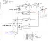
I will correct that later

I am going to etch a small pc board but trying out using fuji photo paper on a laserjet printer.
different project = the motorcycle flasher project that someone was talking about.
On the subject of etching I like using the acid/hydrogen peroxide mixture
not as messy. may take a little longer but works great and is lots cheaper.
will make revisions on schematic and post later today.
 
TINA looks good??

redrew simulation and it is back up to 10+Db
seperate output waves per filter
input mixer (only one showing is still under design
 

Attachments

  • 3-8-2009-7.10.46 AM.jpg
    3-8-2009-7.10.46 AM.jpg
    202.9 KB · Views: 146
Tina & schematic are the same

changed the schematic to match TINA on the op amp #'s
turned off grid as well
 

Attachments

  • Capture3-4-2009-8.30.19 PM3-8-2009-3.17.51 PM.jpg
    Capture3-4-2009-8.30.19 PM3-8-2009-3.17.51 PM.jpg
    179 KB · Views: 150
I guess OP4 is the output mixer. Please label it as a mixer.
The input level control is only 10k ohms and the input opamp has an input impedance of only 47k ohms (is it a mixer too?). Thebn the small value of the 220nf input capacitor cause 89Hz to be reduced -3db and frequencies below 445Hz to be reduced (no deep bass). if the volume control is 100k and the resistors on the first opamp are also 100k then the cutoof frequency will be 14.5Hz when the capacitor is 220nF and will be 9.7Hz when the capacitor is 330nF. Flat down to 48Hz.
 
input mixer circuit

is based on this link
**broken link removed**
need to reconfigure input.
the output "mixer has 5 filter inputs (never really thought of it as a mixer??)
will make suggested changes
as for etching the pc boards -- don't even try using photo paper.
ended up using the PULSAR paper. works great.
when I get this design down pat I plan on using said etching system.
 
The mic mixer you posted has a response that is -3dB at 19.4Hz for the 1uF coupling capacitor into the 10k volume control and each 10uF coupling capacitor into the 1k input resistor. For a voice from a mic this is fine. For music then the deep bass frequencies are reduced.
 
I revised simulation mixer input

arranged circuit as per link (line not mic)
then tried different caps for c7 (see attached)
not sure which is best??
 

Attachments

  • 3-8-2009-6.27.23 PM.jpg
    3-8-2009-6.27.23 PM.jpg
    317.3 KB · Views: 157
  • 3-8-2009-6.26.57 PM.jpg
    3-8-2009-6.26.57 PM.jpg
    316.4 KB · Views: 150
  • 3-8-2009-6.26.20 PM.jpg
    3-8-2009-6.26.20 PM.jpg
    315.2 KB · Views: 189
You do not need C7. Direct-couple the signal from OP3 to the filters.
 
hot dang your good!!

I took it out and simulation is same, no change.
how does the rest of that input look??
remember there are 4 duel pots, 4 - 47 K resistors, 4-1uf caps that all connect to the op3
just like the link **broken link removed**
been redoing the full schematic mixer section.
not sure if I want plugs w/ tails to connect to pots/circuit(hard wire each pot (5 wires to main board per pot) or make a circuit board just for the pots and run one pigtail from pot board to main board (3 wires total (grd, L,R))
the circuit board sound easy but it would need to be double sided.
 
The capacitor C1 should feed each pot, not feed the inverting opamp.

You have two different schematics. One of them was correct a few hours ago except the value of the input capacitor was too low.
VERY confusing.
 
Last edited:
Moved C1 -is this what you mean?

different schematics?? hope this one is the one your refering to.
took out the shorted cap on output as well.
 

Attachments

  • 3-9-2009-2.37.38 AM.jpg
    3-9-2009-2.37.38 AM.jpg
    311.7 KB · Views: 139
mixer schematic is done??

I made all the suggested revisions etc.
now it looks like a mixer?
note that the 2 op amps are op3 in TINA simulation (only one in simulation)
 

Attachments

  • 3-9-2009-8.10.17 AM.jpg
    3-9-2009-8.10.17 AM.jpg
    153.7 KB · Views: 141
The mixer is fine except some of the input capacitor values are only 220nF instead of 1uF.
 
will take a second look see

boy you amaze me - you catch any error
thanks
now to the filters etc.
QUESTION not that it matters but why does the curve change when a different cap goes in for c7?
seems like it changes dramatically
 
Your two or three schematics all have different part numbers so when I said "C7" for one schematic then you are thinking about "C7" on a different schematic.
It is extremely confusing.

The capacitor that feeds the filters is not needed so short it and remove it.
The other "C7" fed the output mixer and your latest schematic has it properly shorted and removed.
The schematic you posted this morning has both capacitors removed.

The VF5 curve changed because it is not an output. It is a virtual ground.
 
Last edited:
The beginning of the waves

are different (have different start points.
due to the frequency response??
Here is the schematic that has the cap values correct?, caps removed as per suggestions
 

Attachments

  • Capture3-9-2009-8.45.19 PM3-9-2009-8.45.14 PM.jpg
    Capture3-9-2009-8.45.19 PM3-9-2009-8.45.14 PM.jpg
    143.9 KB · Views: 146
why the duel supply? for cd4066

Been so long and presently redoing the pcboard using suggestions from this link
Digital Electronics Forum • View topic - A Good PCB Design Reference
The board design is neater and easier to see the circuit instead of a jumbled mess (found a couple of mistakes) but got to the cd4066 and can't recall why use a duel supply?
Something about the input needs to be higher in order for the 4066 to work right?
 

Attachments

  • duel supply.PNG
    duel supply.PNG
    25.1 KB · Views: 135
Your entire project has a dual-polarity supply (it can be re-designed to use only a positive supply). Then the signal averages 0V and swings above (positive) and below (negative).
The input signal to a CD4066 must never be more negative than its supply so since the input signal goes negative then the CD4066 needs a negative supply in addition to its positive supply.
 
In this app using a TL074, a duel supply is better? or am I in need of different op amps for single supply?
Advantages of duel over single supply?
I'm under impression a duel supply has less noise?
 
The power supply for an audio circuit does not cause noise. Single or dual polarity supplies create the same low noise levels.
A single supply circuit has many coupling capacitors to charge so it might cause a POP when the power is turned on or turned off.
A dual polarity supply has coupling capacitors that do not need to charge so there is no POP.
Any opamp can operate from a single supply when it is biased at half the supply voltage.
 
Status
Not open for further replies.

New Articles From Microcontroller Tips

Back
Top