RODALCO
Well-Known Member
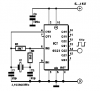
I have had the same problem, couldn't find any data of that IC.
It may have been custom built.
It is a divide by 22 counter with 8 pins.
A CMOS IC 4521 would do the same and let you access other frequencies too.
Clock details where it came out off.
MaxiRex BQT
R 36 h
Ref No 915402
220 V 50/60 hz
contact 16/250
Westdeutsche Elektrogerätebau
West Germany
Made over the period 1985 - 1990 , by now adays standards antique.
Steppermotors would be feasable driving a simple geartrain which can show the difference between the two.
One on the mains, one on the masterclock under test, perhaps a third one on a precision timebase.
The ECS memory masterclock uses a system with planetary wheels which store the pulses when power is lost in an outage and the clock runs on it's own power reserve from the main spring. Power back on and correction is made at one impulse every 2 seconds to advance the minute impulsed dials.
 hm: resistor directly a BC 547 or 2 N 2222 and drive the coil from there.