Continue to Site

Welcome to our site!

Electro Tech is an online community (with over 170,000 members) who enjoy talking about and building electronic circuits, projects and gadgets. To participate you need to register. Registration is free. Click here to register now.

  • Welcome to our site! Electro Tech is an online community (with over 170,000 members) who enjoy talking about and building electronic circuits, projects and gadgets. To participate you need to register. Registration is free. Click here to register now.

Electrically common points on a circuit (equals no voltage)

Status
Not open for further replies.
Just reading and confused about this anyone get it?

not sure really about how it works ( is just a measured phenomenon where there is no explanation just something to remember is true?)
[or is there a fact about the workings of voltage that states this rationally]
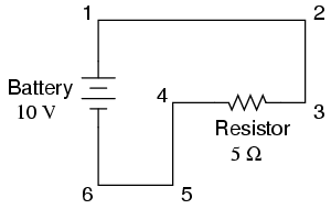
 
ok this is the principal that i am confused with

It says that in an ideal circuit where wire and power resistance is neglected points which are electrically common should be measured to have zero voltage and have very little voltage drop between them.

( points that are not electrically common will be measured as the voltage of the battery so 6-1 will be 10 volts and 4-3 will be 10 volts(neglecting component resistance)( so will 4-2 ,4-1,6-2... will also get 10 volts when measured between the two points)


00050.png

Between points 1 and 2 = 0 volts Points 1, 2, and 3 are (they can be considered as a single wire)
Between points 2 and 3 = 0 volts electrically common
Between points 1 and 3 = 0 volts

Between points 4 and 5 = 0 volts Points 4, 5, and 6 are
Between points 5 and 6 = 0 volts electrically common
Between points 4 and 6 = 0 volts


AND
Between points 1 and 4 = 10 volts
Between points 2 and 4 = 10 volts
Between points 3 and 4 = 10 volts (directly across the resistor)
Between points 1 and 5 = 10 volts
Between points 2 and 5 = 10 volts
Between points 3 and 5 = 10 volts
Between points 1 and 6 = 10 volts (directly across the battery)
Between points 2 and 6 = 10 volts
Between points 3 and 6 = 10 volts


And then the author makes examples of this principle relating to high current voltage lines , why birds don't get shocked and why one side is connected to ground


I think I am just not sure about the why there is no voltage between electrically common points and why birds can stand on power lines.
How would you explain "electrically common" to someone?
 
'Electrically common' means the points have the same electric 'potential'. Thus there is zero 'potential difference' between them. Voltage = potential difference.
A bird on a power line has the same electric potential as the line (say 20kV), so there is no potential difference between it and the line, so no current can flow to harm it. If the bird were able to sit on the line and reach out a wing to touch the pylon (which is at ground potential), then ZAP!


Sorry to trouble you more alec_t

there is something i still don't get. i will try to explain

What I Think Is that Electrically Common Points When Measured Across Have Zero Voltage
00050.png
ok say for example P1 and P2 are electrically common you say that they have the same ELECTRIC POTENTIAL so at both points P1=10vs P2=1ovolts

And then you say that in conclusion that means There is zero "potential difference/voltage" between them so that means when points p1 and p2 are measured on multimeter there should be zero voltage( alright think i am kind of getting it down in theory, just have to remember no voltage across electrically common points right?)

So for the bird it has electric potential(just like becoming one with the wire) but no voltage through it to drive current to the body because it is not connected to the neutral wire and back to the source like the hot wire that the bird is touching is and thus bird not get zapped?[ ok i get the bird thing, it is because bird is not connecting both wires of the circuit ]

Oh this is so confusing....... soo.... isn't electric potential the amount of charge a charge carrier has?
 
onetwothree4, it seems that what you are understanding is basically correct. There is NO potential difference(assume perfect conductors) between points 1 and 3 and NO potential difference between point 4 and 6. Remove points 2 and 5. They are irrelevant and just confuse the issue.
There is a 10v potential difference between points 3 and 4 since that is where the battery is connected.
If you measure between ANY point along the wire 4 and 6 to any other point along the wire 1 and 3 there will be 10v potential difference.
This 10v potential difference will cause a current to flow in the resistor equal to Volts/Resistance and since you have no switch in this CIRCUIT this will flatten the battery in some time. If you had a switch and switched it off the the 10v potential difference could be measured across the open switch and you would have an OPEN Circuit and NO current would flow.
 
On post #3, you did good.

COMMON, ground, chassis, earth are probably all misunderstood and rightly so for someone with a foot in the door.

When sparky measures things, he needs a reference. That ultimate reference is a rod burried deep in the earth where the power company calls that value 0 V for your house only. The ground wire is known as protective ground and it's also known as Earth. Protective ground is used as a reference because it generally doesn't carry current except fault currents.

Aside: Your voltmeter has to carry some current to measure some voltage, but that current is tiny. Many voltmeters that you will encounter are specified as having a 10 M ohm input impeadance. It looks like a 10 meg resistor. Some voltmeters are specified as having a varying input Z of say 50K ohms/volt. Some calibrations that were supposed to be done using the 50K/V meter and done with a 10 M ohm meter COULD be vastly different and wrong.

In the US, neutral (white) is also attached to that ground rod at one point. The neutrals stay separated and the grounds stay separated and aretied together with one big bar at the main distribution panel. Subpanels keep the neutrals and grounds separated in the panel. they are re-united in the main panel.

So, neutral and ground have 0V or very close between them. When they don;t, there are issues someplace.

While we're at it, lets look at GFCI protection. This looks ate the difference of the currents flowing in neutral and HOT. This is done very easily with a "current transformer" . Neutral and HOT are passed in opposite directions through a toroid, thus the difference current is exploited. A few mA across the heart muscle can be fatal.

Your plumbing is also grounded to earth. So, that reference is all around you.

Your cell phone is nearly totally isolated, but the closer it's in contact to a grounded metal appliance, the lower the isolation is. Air has an isolation of about 1000 V per 0.001". What that says is at some voltage and distance, they become one. It might take thousands of volts like from a lightning strike, but they could conceivably connect.

So, I talked a little bit about ground, protective ground and isolation. One day I could be your shoes. The next day it could be a sweaty hand on the ground. protective ground is used in say washing machines. If there happens to be a short that "finds" the case, the alternate path through the ground wire is taken and he fuse should blow.
The fuse is designed to protect the wiring of the house, not the equipment. A GFCI is designed to protect you and an AFCI is designed to "listen: for a spark signature int he hope of preventing a fire. "double-insulated" was later used because plastics are so common. In this case a loose wire inside could not harm you, but a frayed cord could.

In an electronic circuit, there usually are lots of commons. Earth, analog ground, digital ground, high current ground could all be separated internally, but eventually they may come together. Usually this is where we take the power supply to be delivering 0 Volts.

It would be ideal if every common connection went to one screw and every neutral and ground for every outlet in your house to go to the main circuit box, but that's impractical. Some medical offices have orange outlets. the grounds in these outlets are not shared and go direct to the panel. They won;t be a piece of Armour clad cable hitting a metal stud in multiple places. Transmitters and hospitals might actually have two ground busses. One is a reference and one will be fault carrying.

So, the designer usually picks a reference. At one point we had positive ground vehicles. the -48V DC telephone system and AC generation is no accident. AC power transmission corrodes less. Every dissimilar metal in the presence of an electrolyte (salt water) has a potential difference. A battery if you will. This "battery" causes corrosion. Metals at different temperatures have thermal voltages attached to them. When i wave a wire in the air, I'm moving a wire through the Earth's magnetic field. I will generate a current, but it's way too small like maybe 1E-12 Amps. Sometimes things are important and sometimes they aren't.

Your problem above would be vastly different if the currents were 100 amps and resistances <1 ohm and there were wire lengths given.

So, common is a designated convenient point to make measurements. In many cases it's also your surroundings.

The barn 200 feet from the house may not have the same earth as your house in a thunderstorm, but locally it has the same reference. The addition of a ground rod and running a neutral correctly tends to stabilize the difference in potential.

That's a lot to grasp. the key to answering the question you were given is that all wires have 0 ohms resistance. Sometimes 0 doesn't exist. It's a problem and an assumption. Sometimes you cannot use that assumption to solve a problem. You also have to know whether or not what your using to measure the phenomena will change that phenomena appreciably and adjust your methods accordingly.

The bird doesn't get electrocuted, because two parts of his body that likely include the heart muscle in it;s path do not touch the wire and the earth. Where earth is the common point.

Corrected: HOT - thanks
 
Last edited:
This is a little off topic but something I always enjoy watching. You can have a bird on a wire, a man on a wire or sometimes a helicopter and a man on a wire. :)

These guys are working on cross country power lines, each phase can be as high as 500 KV or about a half million volts. Note how as they approach a line the worker extends a rod to the line, note the arc. Since the helicopter is ungrounded the only thing the arc does is get the helicopter to the same potential as the line. You just don't flip a switch and shut down lines like these. :)


https://www.dump.com/repairinglines/

When we look at simple circuits like those shown in the links any voltage drop is negligible. However, when planning power distribution what is known as line loss needs to be considered.

Ron
 
............................
A bird on a power line has the same electric potential as the line (say 20kV), so there is no potential difference between it and the line, so no current can flow to harm it. If the bird were able to sit on the line and reach out a wing to touch the pylon (which is at ground potential), then ZAP!
I have heard that large birds such as eagles have met that fate. :eek:
 
............................................
00050.png
ok say for example P1 and P2 are electrically common you say that they have the same ELECTRIC POTENTIAL so at both points P1=10vs P2=1ovolts

..................................................
The potential at P1 and P2 is 10V with respect to P5 and P6. Remember that a voltage is always between two points (if there is a ground or common point designated in the circuit then it would be with reference to that but that's not the case with this diagram).
 
While we're at it, lets look at GFCI protection. This looks ate the difference of the currents flowing in neutral and ground. This is done very easily with a "current transformer" . Neutral and ground are passed in opposite directions through a toroid, thus the difference current is exploited. A few mA across the heart muscle can be fatal.
You're getting a bit off the topic of the OP's question here, and possibly just adding to the confusion, but I would like to correct a small error in your description of how a GFCI works. The wires passing in opposite directions through the toroid current transformer are hot (a.k.a. live) and neutral, not neutral and ground. As long as the same current (within +/- the device's tolerance) flows through both hot and neutral wires, the current transformer's output is below the GFCI's trip threshold. But when enough current finds an alternate path to earth (such as from a live part exposed to moisture, to a person's hand, to a wet floor or any exposed plumbing), the current flowing in the neutral wire is then reduced by the same amount, so hot and neutral currents are no longer in balance and the device trips. If you understand this, then you will realize a significant safety advantage of a GFCI: it does not require any connection to the protective earth ground wire in order to function.
 
I have heard that large birds such as eagles have met that fate. :eek:
True. In order to protect the endangered California Condor, which is making a comeback from the brink of extinction with a lot of help, many high voltage pylons in and near their habitat have been modified with additional wooden perches mounted above the wires, to give them a safer place to stand and give their wings extra clearance from the wires and pylons.
 
Status
Not open for further replies.

Latest threads

New Articles From Microcontroller Tips

Back
Top