dcwatson84
Member
Instead of the "bumps" picture a depression where a roller microswitch sits along the edge, The micro would stop the motor when sitting in the groove. The timer, just has to give it a nudge for an amount of time less than 1/2 a revolution. If you have a timer with a 1 minute resolution and it takes less than a minute to open the door, the method won't work as designed.
The timer has second resolution. In fact my method relies on that principle as well, but works electrically. The timer needs to "nudge" the door off the switch, since the switch is attempting to shut off the main relay. Once the door is off the switch, the timer can shut off, then the door hits the next switch, this time with the timer off, so it shuts off the main relay again, ending the cycle.
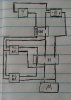
 I don't see how the SPST relay ever gets energised if the lower terminal of its coil (if that's what the hatched thing on its symbol represents?) is connected only to N.O. contacts.