Electro Tech is an online community (with over 170,000 members) who enjoy talking about and building electronic circuits, projects and gadgets. To participate you need to register. Registration is free. Click here to register now.
Welcome to our site! Electro Tech is an online community (with over 170,000 members) who enjoy talking about and building electronic circuits, projects and gadgets. To participate you need to register. Registration is free. Click here to register now.
You must select the "Wire" tool, then select layer 20 and set its width to 0.
This is to draw the dimension of your board.
It will be quite useful when you calculate its size and cost.
Edit: Note that I have Eagle version 5.7, it may appear slightly different in version 5.8
tried the demension 20 etc but keep getting message when trying to move components around?
I get it highlighted but when I attempt to place it says I can't do that.
I am not quite sure what a frame would be used for on a PCB, I can understand its purpose on a large schematic to locate a part by giving its coordinates.
I have never seen a PCB with a frame yet. Does anyone know?
After inporting the schematic into the board it looks like a bunch of tangles wires. Kinda frustrating trying to straighten them all out.
Any easy method to sorting out the jumbled mess?
If you have a small board it is better to route manual as auto route will use 2 layers.
On bigger boards I usually select auto route and then modify and I probably multiply the time I spend by a factor of 10 than if I was doing it all manual but I have a few of these bad habits.
These are the tools manual route on top and auto-route on the bottom.
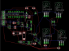
Here is what I have so far. While not pretty with 45s etc it is looking better than it was several hours ago.
need to miter all 90s and get rid of the double trace on the bottom.
scrunch to save pcboard landscape. Should end up with 4 square inches.
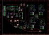
here is a correction of the PCB. I forgot to connect pins 2 and 6.
When routing traces you have several options of trace widths. You might also use a self-defined trace width, which you can put in by overwriting any given selection.
The examples show how to change trace width from 0.4064 to 0.508mm.
can't get rid of the little green square on R5 or 6?
need to miter more 90's(menu that Boncuk posted is ??
How to determine board size?
IMO not bad so far considering the few hours I have spent trying to figure out different aspects of the program.
Next question DRC and ERC
Will ERC work in the board screen and what will DRC tell me?
If you select one of the options just to the right of the layer when drawing a line, it will limit the line to 90 and 45 degrees instead of those interesting angles you have.
I started looking for this menu as John posted but where is it?
Will look some more
All I have tn the area oindicated is a small grid of dots, nothing else to the right.
lost it again??
in miter I get a quarter circle. what kind of miter is that?
and this EAGLE is supposed to be easy? toooo many little options to deal with.
I try and delete but can't?
lots of little idiosyncrasies.
I understand I have weird angles? etc. This is my first attempt at using EAGLE, at least this far.
Here are the files , maybe I can get some guidance as the attributes for angles does not compute? Doing something wrong.
I still need to drill two holes to mount board but determine exact position for using data sheet from PACTEC enclosures
well that didn't work?
Need to compress file or ??
This site uses cookies to help personalise content, tailor your experience and to keep you logged in if you register.
By continuing to use this site, you are consenting to our use of cookies.