Continue to Site

Welcome to our site!

Electro Tech is an online community (with over 170,000 members) who enjoy talking about and building electronic circuits, projects and gadgets. To participate you need to register. Registration is free. Click here to register now.

  • Welcome to our site! Electro Tech is an online community (with over 170,000 members) who enjoy talking about and building electronic circuits, projects and gadgets. To participate you need to register. Registration is free. Click here to register now.

DS1302 (Parallax SX52) 16x16 LED matrix scrolling clock - additional circuitry??

Status
Not open for further replies.
No difference in brightness on original 16x16 display

Mike,

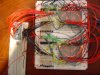
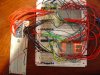
I decided to take my original 16x16 LED matrix (with 2n3906 transistor/resistor) and ULN2803's and replace one row of the transistor / resistor circuit with the new Fairchild P-FET. I had used a 22 ohm resistor from the LED anode row to the Drain. The source went directly to the 5v 20 A power supply (I also tried the whole circuit - logic chips and all). The Gate went to the SX52 bottom row lead (to have it driven by the SX52). The display came on fine with it going into it's normal scrolling. However, the P-FET row had no difference in brightness (fairly dim like the rest - unless it's really dark).

This make's me think that the issue was not that they needed more current as originally it drew less than 100 mA anyway. I believe that the LEDs are just not that bright.

When using the new 8x8 LED matrix modules on the MAX7219 - these are lit up much better than the handsoldered individual 256 LEDs in the first LED matrix.

I suppose the next test should be to simply wire up (4) 8x8 LED modules in the same fashion as the original 256 handwired LEDs as in matrix 1. If they are brighter than the handwired original ones, then the issue will have been with using older (possibly very low MCD) rating.

I will work on this over the weekend and let you know.

PS: The new 5v 20A power supply provides a nice 5.05v out so it appears to be regulated well.

More later...
 
Mike,

This time I took the original design using the 2N3906 transistors/1K resistor/100 ohm resistor BUT replaced the 2N3906 PNP transistors (xx mA?) with the newer PNP 2907A (800 mA) that I got in from Mouser yesterday. I also bought some more breadboards so that I could bread board the (4) 8x8 modules. After I had to rewire it a couple of times to get it right, I also used the new SX48 OEM module (so no soldering was required). I did not connect the DS1302 real time clock for simplicity (it was using default information).

What I noticed was with using the PNP2907 (800 mA) and ULN2803 (500 mA) and measuring total current, it went from about ~60mA or so when onlu displaying 8 rows worth of data to about 180mA when scrolling up the smilley face (using the 16x16 entire display - not just 8 rows to display either time or default date information). I did notice as before that when the smilley face was scrolling - it was somewhat dimmer but not bad (AS IT HAD BEEN BEFORE ON MY OTHER HANDWIRED 16X16 LED MATRIX).

What I am saying is that I have seen relatively no improvements in brightness or significant draw in current. The entire display is also using the internally regulated new 5v 20A power supply. Will less than 200mA I was not too concerned.

If I did change the PNP transistor circuits resistor to 1K-> 100 ohm and original 100 ohm to 10 ohm, yes it was brighter but I am still not drawing 2-5 Amps of current like I expected I would see after using these new parts (2907A PNP transistors and (4) new 8x8 LED modules and 5v 20A power supply).

I only used my original but modified design to demonstrate as a test to see if there were any significant improvements in the display and more excessive current draw.

Im not saying the display is bad (certainly with 10 ohm resistor - it is better in a well lit room) - AND they always look much better in a darker room (e.g. ambient light coming in but overhead lights are shut off) too - I just expected to see more current draw thereby max brightness in the LEDs.

The attached photo's are taken with the lights off as my digital camera didn't differentiate too well between the pictures with the lights on and the pictures with the lights off. Also disregaurd the double images as it was scrolling and it appears bad but it wasn't. Also you will notice the top row of the bottom 8x8 LED modules are brighter (this is because "for that single row only" I changed the 1K to a 100 ohm and the original 100 ohm to a 10 ohm with of course all of the PNP transistors being 2907A).

Also I notice on digtal clocks they always have a red filter lense - maybe this is all that the issue is (to block out light around the display)?

Ideas...comments?
 

Attachments

  • DSC00042.JPG
    DSC00042.JPG
    143.7 KB · Views: 673
  • DSC00043.JPG
    DSC00043.JPG
    149 KB · Views: 546
Tim:

Are the anodes columns or rows in your setup? Are you "scanning" columns or rows (where are the current lmiting resistors? On the PN2907A anode drivers or on the ULN2803 cathode drivers?)

Mike
 
Mike,

See the attached drawing. This is what I am using with the exception of the 2N3906 being now the 2907A PNP transistors (and the row 9 using a 100 ohm instead of the 1K and a {10 ohm - current limiting resistor} instead of the original 100 ohm in the drawing).

The rows are being inverted by the transistor/resistor circuits. The rows are Anodes but require negative signals into the transistor / resistor circuits to get positive signals to the anode rows.

The columns are being scanned and all LED info is being displayed via a software interupt every mSec.

The columns are cathodes and going through (2) ULN2803s which are inverting positive signals into the negative signals that the cathodes needs.
 

Attachments

  • 16x16 LED Moving Display Real Time Clock-Page1.JPG
    16x16 LED Moving Display Real Time Clock-Page1.JPG
    585.7 KB · Views: 3,582
Last edited:
That's what I thought. You're still scanning the cathodes. It doesn't really matter at this point because you're simply not getting enough voltage and 'peak' current to each individual LED to make much difference at this 1/16th duty cycle. At some point however, after you fix the voltage problem or the duty cycle, you're going to have to move those current limiting resistors over to the cathodes and change your code to "scan" anodes as Wilf and I have suggested because those 'source' drivers (PN2907A or FDN304PZ) have the higher current capability.

Let's make it official. My suggestions are (A) or (B);

(A) Use a higher voltage anode supply and 2N7000/FDN304PZ or similar driver pair for each anode. Scan anodes instead of cathodes (cathodes will have the current limiting resistors).

(B) Redesign the matrix for a 1/8th or 12.5% duty cycle (like the MAX7219) where we know a 5 volt supply is sufficient to provide enough 'peak' current to each LED for full-brightness. Scan anodes instead of cathodes (cathodes will have the current limiting resistors).
 
Mike,

As posted on the Parallax web site:

When all the LEDs are on....the LEDs are very dim. I still am being limited to about same amount of current < 200 mA total. This does not change even with the new 5v 20A power supply, ULN2803 (500 mA allowance per leg), PN2907A (800 mA allowance) and (4) new 8x8 LED matrix modules. Wouldn't you think this should be at least 10mA * 256 = 2.56 A ?

I bought all of these high current allowance parts and it still doesn't look like it is drawing more current ???

=====================================
If I simply just move the 100 ohm resistors from the transistor / resistor Anode rows .... to moving them to the outputs of each of the ULN2803's....I can't see how this would make any difference as the resistors are still going through 16 LEDs whether they be anodes or cathodes.

What else concerns me is scaning the anode rows (up and down)....Wouldn't this make all the letters go up or maybe down verses scrolling from right to left (as it does now)?
 
You're assuming all LEDs are lit at once. In a scanning design only ONE row or column is on at any given moment. So on a 16x16 display only 16LEDs are on at any time (10ma x 16 = 160ma), your eyes are slow to respond 40hz approx so your brain sees all the LEDs on at the same time when they are scanned. There are 30LEDs inline on the wheels, turning off and on so fast you see an image.
**broken link removed**
 
Last edited:
I modified my code (as a test) to only scan (1) 4x4 LED Module (8x8 display). It was somewhat brighter. When I did a test to turn on all the LEDs (8x8) I did get more current draw of ~250 mA.

Mike - What do you think about Blueroomelectronics comments?

(e.g. 10mA x 16 LEDs = 160 mA .... which is in the ball park to what I am seeing with all (4) LED matrix modules (16x16 total))

I am getting some conflicting information and need to understand this better.
 
tdg8934 said:
If I simply just move the 100 ohm resistors from the transistor / resistor Anode rows .... to moving them to the outputs of each of the ULN2803's....I can't see how this would make any difference as the resistors are still going through 16 LEDs whether they be anodes or cathodes.
While the resistors are physically connected to 16 LEDs you must remember that you're only ever driving one LED at a time through that resistor.

And I agree that in your 1/16th duty cycle design it really won't make any difference whether you're scanning the anodes or the cathodes (with current limiting resistors on the cathodes or anodes, respectively) because you're simply not going to get the "peak" current you need with 5 volts at that duty cycle.

What else concerns me is scaning the anode rows (up and down)....Wouldn't this make all the letters go up or maybe down verses scrolling from right to left (as it does now)?
Turn the display 90° and tell me what you see. Duh (grin)!

What's really more important is how you represent and manipulate the data in your program and making sure the driver code paints it to the display correctly.

Can I assume you're data bytes are columnar data? That is, bit 0 represents data in a single column for row 1 or row 8 or perhaps row 9 or row 16?

Never mind. That's not really important now. Let me move on to one of your other posts.

Mike
 
tdg8934 said:
I modified my code (as a test) to only scan (1) 4x4 LED Module (8x8 display). It was somewhat brighter. When I did a test to turn on all the LEDs (8x8) I did get more current draw of ~250 mA.
I'm not sure what you actually tried here. What is a "4x4 LED Module"? Are you still using 100 ohm current limiting resistors?

I'm also not sure the current readings you're getting are really meaningful unless you're lighting every single LED in the matrix.

All I can say is that you should be able to get full brightness with a 5 volt supply on an 8x8 matrix using ULN2803's or MIC5821's on the cathodes and 2N4403's or PN2907A's on the anodes with a 1/8th duty cycle. I've done it and I suspect you realize it can be done because you've seen it on a MAX7219.

If it will help, perhaps I'll breadboard an 8x8 display and drivers next weekend.

More later, Mike
 
tdg8934 said:
Mike - What do you think about Blueroomelectronics comments?

(e.g. 10mA x 16 LEDs = 160 mA ....)
Bill (BlueRoom) doesn't always do his homework (grin) and obviously isn't thinking in terms of "duty cycle" and "peak current".

I am getting some conflicting information and need to understand this better.
I agree on both points (grin)...
 
Mike,

In your comment about using 4x4 LED module - that was a mistake. I meant to say that I only scanned or used the 1st of 4 (8x8 LED Matrix modules). This was brighter and gave me 250 mA when turning on all LEDs by scanning them fast. I am still using 100 ohm current limiting resistors (except for row 9 which is using a 10 ohm - but in this case rows 9 - 16 and columns 9 - 16 are not being used).

Data was only being sent into the rows while the columns were being scanned every msec.

On the MAX7219 it is about the same decent brightness as when I scanned only (1) 8x8 LED module. But should I not see more current with all the LEDs on being 2.56 Amps (=16 columns "cathodes" scanned * 16 rows "anodes" all being "1s" (or on)) ??

Maybe what I am getting at is that my scrolling clock has very bright LEDs being displayed - but it also has a dark red bensle lense over the front of it too like most other digital clocks do. I'm just thinking that I should have more current going through my project and should the LEDs be as bright as my scrolling clock or is it normal the way it is?

And about the letters scrolling up or down - I was concerned that the letters would still face up and down and the whole 16x16 LED display would scroll up. I think you were thinking that the letters would rotate 90 degrees too. I just did not know what would happen with that - that's all.
 
blueroomelectronics said:
Just curious, what is the peak current for those 8x8 displays at 1/8 duty?
Hi Bill:

If 10-ma current gives you the brightness you want on a single LED at 100% duty cycle then a "peak" current of 80-ma would provide similar brightness at a 12.5% (1/8th) duty cycle. If all 8 LEDs in a "scan" column or row are lighted then the column or row driver will need to source or sink 640-ma "peak" current.
 
Last edited:
Right - and currently with only 1 8x8 LED matrix being scanned, I am only getting 250 mA max current when all the LEDs are perceived as being "on". This is a far cry from 640 mA.
 
Tim:

I'm not sure the ammeter portion of my DMM is working but I'll try to hook it up to my solderless breadboard and see if I can get a reading with the 1/8th duty cycle circuit that's on there now (A6841/MIC5841 and 2N4403 drivers in a 1/8th duty cycle configuration driving 7-segment displays).

I just powered up that circuit a few minutes ago and I was able to turn up the brightness enough to overload the 5 volt 1 amp power supply I had connected to it.

Mike
 
Last edited:
Mike,

How do you "turn up the brightness"?

I had made some changes to my design as I remembered I had Allegro Microsystems send me some UDN2892s. These are basically the un-inverted version of ULN2803s. I have them on my rows in replacement of my (inverter transistor/resistor circuits). Since the UDN2892s dont invert (500mA driver) they work great. However, I did remember to add in the 100 ohm current limiting resistors on their outputs going into the LED row Anodes. I did have to un-invert my rows in my software interupt. Currently I have a smiley face scrolling up on the 16x16 LED matrix as a test. It has the same "dimmer" brightness as I had before when I used the inverter transistor/resistor circuits.

I think as a must I am going to use 10 ohm resistors and not the 100 ohm current limiting resistors on the outputs of the rows. I suppose I could instead place them on the outputs of the column cathode drivers (ULN2803s) if you think this would help?

When the smiley face scrolls up and stays on the 16x16 LED matrix for 2 seconds, the most I get is < 100 mA total current.

Love to hear back from you on this adventurest quest of mine!
 
Mike,

I got my A6821 Allegro Microsystem samples today and at some point soon, I want to modify my code to use them instead of the ULN2803s. I will also get my purchased from Jameco 74HC574s on Wednesday - as per Wilf.

I need a way to control the red as well as the green LEDs and I think this may be the way to go - else using the A6821s.

I don't like the idea of re-inventing the wheel with writing new code just for clearing up more I/O - but I think it is a necessary evil that needs to happen at some point.

I also purchased some 1/8" smokey grey plexiglass for the 8x8 modules. I need to also start looking at some PCB design program. I will probably use ExpressPCB but I need to learn it a little first.

Tim
 
Strange current occurance?

As a test I wanted to see what would happen if I lowered (1 of the 16) - 22 ohm resistors my matrix is using to a 2 ohm. Surprisingly I saw no difference in brightness. The brightness is lowered when 5 or more LEDs are on a column.

As another test, I removed the resistor and still saw no difference. I started removing all of the 16 current limiting resistors and so there were no resistors (just 16 anodes, 16 cathodes, 2 UDN2982s and 2 ULN2803s going to 32 I/O lines of the SX52.

What I did notice is that the current was measured previously at ~300 - 640 mA. Now it appears to be about 20-30 mA.

Does this sound right?

On a side note....I etched a custom soldering board with 16 of the surface mounted P-Channel 2.4A FETs as described earlier. I will take out the UDN2982 and try using this double sided PCB (8 P-FETs on each side) and see if this helps. This means there will be (as a test)...16 Anodes, 16 Cathodes {LED matrix 256 LEDs total}, ULN2803 (2) - {probably should add back the 16 - 22 ohm resistors - but this time put them on the outputs of the ULN2803s not the UDN2982s - that are replaced with the P-FETs}. Do I need to pull up 1 K resistors on the Gates of the P-FETs?

Thought...Comments.
 
Last edited:
Status
Not open for further replies.

Latest threads

New Articles From Microcontroller Tips

Back
Top