Continue to Site

Welcome to our site!

Electro Tech is an online community (with over 170,000 members) who enjoy talking about and building electronic circuits, projects and gadgets. To participate you need to register. Registration is free. Click here to register now.

  • Welcome to our site! Electro Tech is an online community (with over 170,000 members) who enjoy talking about and building electronic circuits, projects and gadgets. To participate you need to register. Registration is free. Click here to register now.

DS1302 (Parallax SX52) 16x16 LED matrix scrolling clock - additional circuitry??

Status
Not open for further replies.

tdg8934

New Member
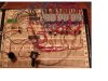
I have completed a 16x16 LED matrix scrolling clock display on a $10 Parallax SX52 Protoboard and micro-controller. It uses a DS1302 Real Time Clock and 32KHz crystal for accurate stability in keeping track of the time and date. This is all working well as you can see in my attachment zip. Also here is an older version of the design from YouTube.com:

https://www.youtube.com/watch?v=HtUVlkJdNwM


Here is my new challenge:

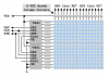
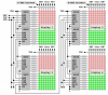
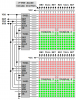
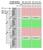
I have recently purchased some 8x8 LED modules on Ebay that are bi-color. This means for my 16x16 LED display, I would have 4 modules giving me 16 row anodes (which I use transitor/resistor drivers) and 16 rows of cathodes (which I use ULN2803 drivers) of either RED or GREEN LEDs (which really mean I have 32 cathode lines of collumns) to my SX52 microcontroller (all programmed in SX/B - SX Basic with an interrupt routine). However, since this microcontroller currently uses RD and RE for the 16 rows of cathodes and RB and RC for the 16 columns of anodes (as well as 3 interface lines of RA for the DS1302), I only have 5 additional I/O lines (RA.3 - RA.7) left. I need 16 additional lines of column cathode output I/O lines for the bi-colored LEDs.

Is there any circuitry available that can take the 16 output lines from RB and RC and switch them into 2 banks of 16 output lines (32 total outputs) that are controlled through something like an enable line (e.g. 0 = turn first bank on for green LEDs, 1= turn 2nd bank on for red LEDs). However, the ideal situation is to have 32 I/O outputs where I only have 16 currently for the collumns. The reason is that I would like to have it running fast enough to appear that both red or green individual LEDs could be on and not just one or the other. The enable line might be controlled via an unused RA I/O line on the SX52.

I realize that many of you may not be familliar with the Parallax SX line of micro-controllers (but in this case I am concerned more on the hardware external circuitry) and you can think of the SX52 is more or less a PIC chip (which I am only vaguely familiar with PIC chips).

Any ideas on what chips should be used to do this?
 

Attachments

  • DS1302 SX52 16x16 LED matrix scrolling clock .zip
    323 KB · Views: 5,518
Last edited:
You might look at data sheets for the cascadable 74HC595 serial-to-parallel 8-bit latch to drive your transistors and ULN2803 devices. Or use an 8-bit serial-to-parallel sinking driver with a 3 pin interface (Data, Clock, and Strobe) in place of the ULN2803 sinking drivers.

Right now, it seems you're "scanning" columns of 16 LEDs at a 1/16th (6.25%) duty cycle. Unfortunately your ULN2803 sinking column drivers are seriously under rated for the 2.5 to 5.0 amps 'peak' current required to light all 16 LEDs in a single column to full brightness. If I were forced to design a 6.25% duty cycle 16x16 matrix I would turn it around like the drawing below and "scan" anode columns with 5-amp P-FET drivers and use the MIC5821 sinking drivers on the cathode rows where the drivers only need to provide about 320-ma "peak" current on each pin when lighting a single LED.

16x16-matrix-2-png.12466


You should consider changing the design from "scanning" 16 columns of 16 LEDs at a 6.25% duty cycle to "scanning" 8 columns of 8 LEDs at a 12.5% duty cycle to reduce the peak current requirements and get better brightness.

The Micrel MIC5821 or pin-for-pin compatible Allegro A6821 are very much like a ULN2803 sinking driver but with a cascadable 3-pin interface (Data, Clock, and Strobe).

**broken link removed**
 

Attachments

  • 16x16 Matrix (2).PNG
    16x16 Matrix (2).PNG
    19.5 KB · Views: 24,870
Last edited:
New 16x16 LED matrix design

Mike,

I am currently soldering up a new matrix of 4 8x8 LED modules (bi-color) but using TPIC6C595 high current version of the 74HC595 (different wiring though). I am also using ULN2803's for columns. I am scanning all 16 columns because sometimes I may want to scroll the top 8 rows, sometimes the bottom 8 rows and sometimes scroll upwards the entire 16 rows. If I only scan 8 rows at a time, it may be difficult in coding to accomplish this for scrolling upwards the entire 16 rows. I will let everyone know of my progress. However, what I am not possitive about is whether the 1 amp power supply is enough current. It seemed to be ok before but I never knew if the LEDs I used before were slightly dimmer because they were older LEDs. I am now using 4 8x8 LED modules so hopefully they will be newer technology therefore brighter with a higher MCD rating. Although I bought them on Ebay so I don't know the specs for sure.
 
You seem to think the way you drive the hardware is related to how you manipulate the display data for scrolling or other special effects. The two are not related. Your hardware driver should be a simple and invisible interrupt driven background task that simply paints your display data onto the display hardware. You should design your hardware as a compromise between best performance, fewest components, and minimal I/O.

You seem to realize you're not getting full brightness on your displays. Here's why; If you need 10-ma to light a single LED in your 16x16 matrix to full brightness at 100% duty cycle, you're going to need a "peak" current of 160-ma to light the same LED to full brightness when driven at a 1/16th (6.25%) duty cycle. Your column driver will need to be able to sink that 160-ma "peak" current for each of the 16 LEDs in that column. That's approximately 2.56 amps. That's beyond the 500-ma/pin rating of your current ULN2803 sinking column drivers, beyond the 160-ma/pin rating of your proposed TPIC6B595 sinking column drivers, and beyond the limit of your 1-amp power supply. In short, you're simply not "working the numbers".

I was amazed when I cobbled together my first full brightness design and found that I could force the 1.5-amp regulator into overcurrent shutdown as I turned up the PWM brightness control.

Anyway, here's one possible full-brightness solution for your 1/16th (6.25%) duty cycle dual-color 16 by 16 matrix. Requirements are;

<added> a higher supply voltage may be required for displays with duty cycles less than 12.5% ???


(1) Power supply; 5v (?) at 5.0-10.0 amps (assuming 10-ma or 20-ma per LED, respectively).
(2) P-FET column drivers; 5.0-10.0 amps (assuming 10-ma or 20-ma per LED, respectively).
(3) MIC5821 row drivers; 160-320 ma per pin (assuming 10-ma or 20-ma per LED, respectively).
(4) Interface; 19 pins (16 column driver and 3 data pins).

(*) You can use the 160-ma/pin TPIC5B595 drivers if 10-ma per LED provides "full brightness".

matrix-16x16-2-color-1-png.12490

You might consider splitting up the design a little to reduce the P-FET requirement from 5.0-10.0 amps per P-FET to 2.5-5.0 amps per P-FET.

matrix-16x16-2-color-2-png.12489


And here is a 1/8th (12.5%) duty cycle dual-color 16 by 16 matrix design and requirements;

(1) Power supply; 5v at 10 amps (assuming 20-ma per LED full brightness).
(2) P-FET column drivers; 2.5 amps (assuming 20-ma per LED full brightness).
(3) MIC5821 or TPIC6B595 row drivers; 160 ma per pin (assuming 20-ma per LED full brightness)
(4) Interface; 11 pins (8 column driver and 3 data).

matrix-16x16-2-color-3-png.12476


I hope you are able to "beef up" your power supply and come up with a nice high performance design. Please let me know when you get there and I'll tell you how to implement an extremely simple PWM brightness control with full fade-to-black capability.

Regards, Mike
 

Attachments

  • Matrix 16x16 2-color (3).PNG
    Matrix 16x16 2-color (3).PNG
    170.4 KB · Views: 24,535
  • Matrix 16x16 2-color (2).PNG
    Matrix 16x16 2-color (2).PNG
    39 KB · Views: 14,833
  • Matrix 16x16 2-color (1).PNG
    Matrix 16x16 2-color (1).PNG
    36.1 KB · Views: 16,464
Last edited:
I should mention that if your 8x8 dual-color displays are common cathode instead of common anode, you're screwed. I simply haven't found any "source" driver ICs similar to the MIC5821 or A6821 serial-to-parallel sinking drivers, which is really a bummer.
 
Opened my eyes!

Mike,
You certainly have opened my eyes on this one. I have built a couple of LED display signs based on some designs I have seen on the internet. No one has gone into this detail as you have - especially the high current ratings.

I need to do some shopping online for some P-FET anode drivers and probably a good 10 Amp power supply including the 5821's. Do you have any good sources where I can look for these? I normally shop online at Jameco but I certainly want to learn from the Master!

I will do some research and see what I can find if you can tell me if they will fit the requirements.

My 8x8 bi-color led matrix modules were purchased on Ebay. I have no idea whether they are 10 mA or 20 mA rated.

Since my SX52 microcontroller has it's own 7.5vdc 1 A power supply (regulated down to 5vdc). It sounds like I will need to have a common ground between the display/LEDs board (with it's 10 amp P/S) and the microcontroller protoboard (with it's 1 amp 7.5vdc to 5vdc supply).

What size wire should I wire the LEDs to the IC's. I have been using 50 wire ribbon cable from an old Hard Drive (probably 24 guage). Do I need to use something heavier for the 10 A p/s requirements? It's hard enough to solder this with the rats nest of ribbon cable I have now. Let me know...

Back in a little while...

Thanks again for your eye opening exposure to this project of mine.
 
Power supplies are expensive

Mike,

I see that DigiKey sells the Micrel MIC5821. However, I can't find a "reasonably" priced 10A 5vdc power supply on Digikey. Most are in the hundreds of dollars.

I did find this 20A 5vdc power supply on Ebay:

**broken link removed**

Do you have sources for all of you parts in your designs?

This is more expensive than I anticipated and hard to find parts too.

I still don't understand why I can get an "OK" scrolling display message brightness using my current design (using 1 amp power supply - not the massive 10 amp that you state). Maybe it is not at 100% brightness but it won't cost a fortune either. There has to be a mid point somewheres.

I would love to hear back from you on this Mike.
 
Before you start throwing money at your design you may want to make sure you have common anode displays first.

You're getting "OK brightness" on your underpowered displays because each LED still throws off quite a bit of light even when it's only being driven with 2 or 3 milliamps "average" current.

I think just about every LED I've seen has a 20-ma spec' except for some special low current Fairchild or Agilent 7-segment displays. Fortunately there's not much perceived difference in brightness when driving most LEDs at 10-ma or 20-ma and so I tend to drive the displays at a nice safe 10-ma "average" current using one of a few surplus 5 or 6 amp laptop power supplies I've collected these last few years.

Several manufacturers have TTL level input low Rds P-channel MOSFETs in the 5 to 10 amp range. I sampled some Fairchild 2.4 amp FDN304PZ devices in an SMD package but IR (and others) also have some great devices. I'll look for some valid part numbers for you.

Good luck. Regards, Mike
 
Mike,

I have (2) 16x16 LED displays. The first one I handwired out of 256 LEDs from (3) - "XC556R-100" JimPak 100 pk of LEDs (.200 Dia Red T 1 3/4). These LEDs are 1.5 MCD at 10 mA as what the front label says. I have this wired up as per my previous posted schematic. As this MCD appears to be very low I thought that may be the reason for the "dimmer" but almost acceptable display. I have seen other very bright LEDs listed on the internet at hundreds or thousands of MCD for its brightness so 1.5 appears almost non existant compared to the other "newer" ones on the internet. This handwired 16x16 display had it's rows driven by (16) 2N3906 transistor / resistor inverters basically (neg input provided pos input to the Anode rows). While the columns were cathodes driven by (2) ULN2803's (pos input provided neg input to the cathodes).

Look in my first posting for my YouTube video link to this display.

https://www.youtube.com/watch?v=HtUVlkJdNwM

As you can see the lights are off but there is some background light in the room. However, in a fully lit room - the lights are not as visible as a darker room would be (as I would expect).

The other display are made up of (4) 8x8 modules that are bi-colored from Ebay. The bi colored LEDs are connected together at the anodes and I was going to connect them in a similar fasion to the first hand wired 16x16 LED matrix. This means the 16 anode rows would be drived slightly different by using (2) TPIC6C595 IC's and the 32 columns (16 green and 16 red cathodes) were to be driven by (4) ULN2803 IC's. I have it all wired up but not to the Parallax SX52 microcontroller to test it. So any changes to my design need to happen soon before I do any more wiring.

Also I have a single chip (no high current driver ICs) PIC chip based scrolling clock (came in a KIT form from Velleman) that only uses 70 LEDs (10 x 7) but these are "very" bright in it's display. Is this because they may have a higher MCD rated LEDs? The power supply is only 210 mA not the 5 or 10 A that you stated before. Yes I understand there are less LEDs but a 210mA to 10 A power supply jump is a huge leap forward in price and size.

I was able to find a 2 Amp 5vdc power supply from a Linksys print driver that I used on my handwired display. Since it was 5 vdc I could NOT bring it into the SX52 protoboard using the standard 7-9 vdc - 1 A regulated down to 5vdc. This SX52 protoboard also allows for a Vin connection of 5vdc WITHOUT going through the 1 A regulated powersupply. I connected this and saw little if any difference in the display brightness. I then measured the current draw to be between 35 mA and 90 mA depending on how many LEDs were on while column scanning the 0 to 16 LEDs possible at any one time. As the software is Interrupt based scanning every mSec, I thought that only 0 to 16 LEDs (up and down) per column were on at any one time. Therefore it should only be 16 * 10 mA or 160 mA which makes sense with the current readings I got.

Is there anything else I should test or look at here?

Beleive me I am not trying to argue just to understand why a 10 A supply and 5-10 A P channel FETs are needed if I am only drawing less than 100 mA. Am I really missing the boat somewheres?


Finally - Does the Ebay 20A 5vdc power supply (last post) look acceptable? I very much apreciate your help in making me understand this better. I think at the moment it isn't clicking because I am not seeing a huge current draw.

Do you think it is because of not using the FETs allowing for more current to be drawn? So many designs I have seen have used the ULN2803 or something similar and no one says anything about a 5 or 10 A power supply.


Please help me understand and provide any part numbers and sources you can.

Thanks so much!
 
Last edited:
First, I think the TPIC6C595 is an open drain low side sinking driver, much like the ULN2803 and the MIC5821 devices. You can't use it as a high side sourcing driver on your anode rows.

I suppose you could be correct about the low MCD rating on those discrete LEDs affecting the overall brightness of your first matrix. I've really only experimented with a handful of different type discrete, 7-segment, and 8x8 matrix displays these last couple years.

You'd have to show me what the Velleman kit hardware looks like before I could tell you how they're making best use of that 210-ma current.

You're correct, only 16 LEDs are lighted at any one time on your current 2N3906/ULN2803 16X16 board. You should be able to drive those LEDs much harder than the 90-ma average current you're seeing. You can't really increase the 5v source while using those PNP drivers so you might try decreasing the value of the current limiting resistors from 100 ohms to some other value as low as 10 ohms. Try replacing the current limiting resistor in just one or two rows then observe the difference. The limiting factor in that design is probably the 500-ma per pin sink limit on the ULN2803's. If you could get all 500-ma while lighting all 16 LEDs in each column that would work out to 31.25-ma per LED once every 16 "scans". That's still only about 2-ma "average" current per LED but you'll definately notice the difference.

Finally, the specs' I provided were for "peak" current required to light all 16 LEDs in every column to full brightness or to near full brightness (10-ma "average" current). Since we'll probably never be lighting all 16 LEDs in every column at the same time in real world applications we can probably factor that 5 amp power supply requirement by 50% or so. I wouldn't recommend that in a commercial product when liability issues come into play but it's probably fine for our hobby applications where every penny counts (grin).

More later. Regards, Mike
 
Last edited:
Mike,

Thanks for the info. Here is the link to the Velleman clock I have. The LEDs are much brighter than what is shown in the picture.

**broken link removed**

schematic here:

**broken link removed**

It sounds like I will have to unsolder the connections going to the 2 TPIC6C595 on the new (4) 8x8 bi-color LED displays (16x16 total). This leaves 4 ULN2803s to drive the cathodes (16 green LEDs and 16 red LEDs) and nothing so far to drive the 16 anodes for the moment.

I had in an earlier design used 10 ohm resistors (instead of the 100 ohm) on the transistor / resistor circuit for the anodes which did make the display somewhat brighter. As you can see from the schematic in the first posting, the transistor / resistor drivers I currently use on my handwired 16x16 LED matrix use 1K ohm from the microcontroller to the base, and 100 ohm from the collector to the LED anode. I had also used high current PN200 transisors but noticed the same display brightness if I used commonly available from Radio Shack (2N3906) resistors.

I am not clear on what are you saying I should do with this circuit? Use my new Vin 5vdc 2 A power supply and use transistor / resistor circuits using 10 ohms? Or can I continue to use my 7.5vdc 1 amp p/s regulated on the SX52 proto board to 5 vdc (this is my prefered method for ease of use).

Do I need to get a 5 A or 10 A 5vdc power supply ? Do I need to get P channel FETs at 5 A rating?

Thanks!
 
I really don't want to tell you to buy a 5 amp power supply. Our meager hobby budgets pretty much dictate that we make every penny count. I just automatically collect every discarded power brick I come across and I've been fortunate to find some "broken" high current Compaq and Dell laptop bricks that were repaired simply by opening them up and reflowing cold solder joints on the AC connector jacks. Any "cheap" surplus high current bricks available on ebay?

I was afraid you were trying to use the TIPC6C595's as source drivers. Ouch! That certainly puts a kink in your design. Well, you might go back to PNP transistors but something with a little more current capability. Doesn't the inexpensive 2N4403 and PN2907A handle something like 600-ma and 800-ma, respectively? Looks like the 2.4 amp Fairchild FDN304PZ goes for 56 cents (qty 1) at Mouser but it's an SMD package. Just not sure what to suggest. Sorry.

More later. Mike

-- can't seem to download that Velleman schematic. both Kit123 and Kit124 seem to be 5X7 matrices and not 10X7 matrices. perhaps I'm not looking in the right place?
 
Mike the FDN304PZ from Fairchild Semiconductor is rated at 2.4 A and 1.8v. Doesn't this have to be a 5A and 5 vdc? Why choose 2.4 A - currious and 1.8v through me for a loop in figuring this out too.

So if I get a 5vdc 5 A (or even the 20A power supply brick from Ebay), this is only needed if I get the P channel FETs? Will purchasing the higher current power supply this show an increase in brightness in my current design using 2N3906 transistor / resistor circuits for the Anode rows and ULN2803 columns? OR must I get the power supply AND FETs - otherwise all bets off with my current layout.

Also - I see what you mean about the TPIC6C595. It only provides 100mA per channel (good for 8 10mA LEDs - but not for 16 10mA LEDs). I will have to remove this from my other (4) 8x8 LED matrix setup for sure. It looks to me that the MIC5821 is similar to the TPIC6C595 which is similar to the 74HC595 (with inverters on the 595 outputs) - just more current output (100mA on the TPIC6C595 and 500mA per channel on the MIC5821). However I can probably use the ULN2803 and not go serially in like the MIC5821 for the time being too as I have plenty of I/O on the SX52. But this is certainly good to recognize this. Thanks for that clarification.

Try this site for the Velleman MK123 to see it:

http://www.mbelectronics.com/article.aspx?id=63

Let me know if you have troubles.

Also let me know about the 5A or 20A p/s and FETs...


One more thing....

Another engineer on another forum has also been looking into this issue for me. Here is his findings:

http://www.ts1000.us/cgi-bin/yabb/YaBB.pl?board=PROJIDEA;action=display;num=1176295563;start=0#8

Look at his last posting - especially his 74HC574 circuit in his link.

He also recommends using the PN2907A like you did too.

What do you think about this? He says there is 1/32 scan rate and you said I should try to keep it at 1/8. I am a bit confused about this.

Thanks so much for your excellent help.

Thanks again.
 
Last edited:
Mike,

I took the plunge and got the Ebay 5vdc 20 amp power supply.

Since I now have the power (no pun intended. lol).... what else should I get, FETs (please explain your reasoning on the 1.8v 2.4A one you stated earlier). How about the the previous post with my questions too.

Take care - I very much appreciate you good input and help on this confusing project.
 
Those posts were extremely interesting. Thanks. Wilf knows much more about electronics than I do. I suspect his 10 chip 1/32nd duty cycle design may work fine but that's too many chips and too low a duty cycle for me (grin).

He also thinks in terms of "average" current even on the drivers which was very enlightening. It might explain how I managed to get much more than the 600-ma spec' through the 2N4403 PNP column drivers in the experimental Clock circuit below.

The "peak" current through any one of the 2N4403 column drivers should have been around 560-ma at full brightness (10-ma "average" current per LED, 1/8th duty cycle, and 7 LEDs per column) but I omitted the current limiting resistors when I bread boarded the circuit thinking that I would just keep the PWM brightness setting turned down low.

Later when I added code to adjust the PWM brightness setting I couldn't resist adjusting the setting upward from the original fixed 50% setting. I was amazed when the LEDs became bright enough to project light onto a good portion of the Lab bench (grin). And when the 5 volt 1.5 amp regulator finally went into overcurrent shutdown I realized I must have been getting well over 1 amp "peak" current through each 2N4403.

So, I wonder if an 800-ma 2N2907A anode driver might be capable of handling the 2.5 amp "peak" current at 1/16th duty cycle in your design? Yes, no, maybe, huh?

**broken link removed**

BTW, while the schematic doesn't show them, there are 510 ohm base resistors on the 2N4403 column driver transistors.

Later, Mike
 

Attachments

  • Concept - Clock breadboard.JPG
    Concept - Clock breadboard.JPG
    276.9 KB · Views: 1,569
Last edited:
OK. It sounds to me that I should order some 2N2907A transistors instead of the FETs.

What makes me a bit worried about this is that I used some PN200 on another 7x20 LED display using PN200 for the rows (1K and 10 ohms) and (3) ULN2003. I used my 1A power supply and I got about the same brightness as before. I am assuming this is because of the 1 A power supply. However, if my 16x16 LED display (256 LEDs) I have now draws 90 mA then this (only having 140 LEDs should have drawn much less). BTW this display went into a 4017 and 4081 to scan the columns (ULN2003 based) and RB to scan the rows (PN200 and resistors based).

What am saying is that I have used a similar approach using the high current transistors (sorry - no PN200's left - but the 2N2907A sounds like it has a bit more current) and never saw any brightness difference - maybe somewhat more when I changed from 100 ohm to 10 ohm resistors in the row drivers.

What do you think about Wilfs approach (vs your 5821 / 2N2907A approach)?

I gladly welcome all you have to offer in knowledge!
 
On Digikey I found some good high current PNP transistors:

TIP32C TO-220 3A 100V $0.50 each or 25 for $9.45

https://www.digikey.com/scripts/DkSearch/dksus.dll?Detail?Ref=110739&Row=1083633&Site=US


PN2907ARLRAG TO-92 600mA 60V $1.70 for 10 (probably need 20)

https://www.digikey.com/scripts/DkSearch/dksus.dll?Detail?Ref=110739&Row=899449&Site=US


MPS751RLRA TO-92 2A 60V $2.56 for 10 (probably need 20)

https://www.digikey.com/scripts/DkSearch/dksus.dll?Detail?Ref=110739&Row=816604&Site=US


Is it best to get the highest current rating that I can afford (e.g. 3A to cover the 2.56A worst case for all LEDs on?)

Please let me know what the best way is to go with this.


Also DigiKey carries the MIC5821....

Thanks again!
 
Wilf's 74HC574 latch design provides a very simple and fast interface to the microcontroller but it's just too darned many chips and way too low a duty cycle for me. The '574's do have output enable pins (like the MIC5821's) so it would be very easy to add PWM brightness control.

I suspect your brightness problems are a result of the incredibly low duty cycle. In my experiments I noticed a tremendous decrease in brightness when going from 20% duty cycle (5 columns) down to 12.5% duty cycle (8 columns) and that's when I pretty much decided that anything more than about 10% duty cycle was incredibly demanding. Perhaps it requires more than 5 volts in order to get the "peak" current required?

If you wanted to try a higher voltage on the displays you'd have to use two transistors per column or something like the 8 bit 500-ma UDN2981 'source' driver IC's which have TTL inputs and outputs that'll source up to 50 volts.

So, perhaps my suggestions for a full brightness 1/16th duty cycle design at 5 volts might not really give you full brightness. If that's the case, I'm sorry!

Are the 1/8th (12.5%) duty cycle designs starting to sound any more appealing yet (grin)?
 
Last edited:
Mouser.com

25 each Fairchild PN2907ABU TO-92 800-MA 60v --> 0.05 ea, 1.25 extended


Please ask friend Wilf or other Forum members here about the transistor selection. I'm sure everyone knows more about analog electronics theory than I do.
 
Last edited:
Mike,

I am in agreement with you about the low duty cycle as one reason why the brightness is lower than it should be. As a test I can probably modify my current code to scan only 8 columns (or anything else except 16) and see if the brightness is any better. I will do this tomorrow night after work and let you know my findings (if you think this will help).

What is "Pulse Width Modulation" brightness control? Is this something you add via hardware or a software technique? Remember I am not using a PIC chip and my code is written in SX Basic with a 1 msec interupt for the display.

I dont think I can use a higher voltage on the display as I just purchased the 5vdc 20A power supply and have to maintain 5vdc for the SX52 micro-controller, ULN2803, etc..

With the addition of the new PNP transistors (I will post the message to others about the PN2907A variant), wont this allow more current to pass thereby increasing brightness? If so then should it mater so much what the scaning rate is then (e.g. 1/8, 1/16, etc..). Remember I have really 16 red and 16 green LEDs that will have to be scanned too in some capacity I believe (as Wilf shows).

Comments....
 
Last edited:
Status
Not open for further replies.

Latest threads

New Articles From Microcontroller Tips

Back
Top