Continue to Site
Follow along with the video below to see how to install our site as a web app on your home screen.
Note: This feature may not be available in some browsers.
How hard is it to take 5 minutes to do some research, when the place to do the research and the search criteria have been given to you?
This is what I found, doing 30 seconds of searching on Youtube, like I instructed you to do and you ignored. Again.
YouTube - How to Hand Solder a QFP, Part 3
1. First is the solder mask. It can handle the 700°F of the solder and that keeps the toner system from working this type of board. This needs a silkscreened epoxy or silicon based formula as the soldermask. This is one big reason I am working on the photo method. 2. Second, the IC's and other components are accurately placed and glued down. 3. Third, the use of a liquid flux. This in of itself is the reason this works on pretinned surfaces.Why do you care about solder mask? It's not essential.Yes I see now and thank you. What still is lacking is three items that are critical.
First is the solder mask. It can handle the 700°F of the solder and that keeps the toner system from working this type of board. This needs a silkscreened epoxy or silicon based formula as the soldermask. This is one big reason I am working on the photo method.
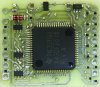
You are assuming this, like you assume everything based on no research or evidence.Second, the IC's and other components are accurately placed and glued down.
I have no idea what this sentence means or why this is "critical".Third, the use of a liquid flux. This in of itself is the reason this works on pretinned surfaces.
It's not hard and many people can do it. You think it's special because you haven't done any investigation at all.I am very impressed that you are able to solder these components down on rough pads with no soldermask. You get a lot of credit for that.
")
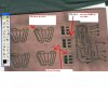
Originally Posted by DirtyLube
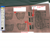
, I circled (actually squared) in orange places I also think problems occur. I also would be interested in some better pics of Mr. Deb's finished product.