Continue to Site

Welcome to our site!

Electro Tech is an online community (with over 170,000 members) who enjoy talking about and building electronic circuits, projects and gadgets. To participate you need to register. Registration is free. Click here to register now.

  • Welcome to our site! Electro Tech is an online community (with over 170,000 members) who enjoy talking about and building electronic circuits, projects and gadgets. To participate you need to register. Registration is free. Click here to register now.

Discharging effects

Status
Not open for further replies.
When i use AC meter to measure current the + and - signs alternate back and forth

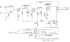
I hook up a function generator 5volts p/p into the input of the guitar schematic i posted when measure AC current if the signs are alternating how do u know which way the current is going then?

Can someone please draw some arrows please this would help me out alot to understand AC current more and discharging current more

*** DC discharing is way different than AC discharging what is the difference?
DC discharging Times VS AC discharging Times?
 
walters said:
When i use AC meter to measure current the + and - signs alternate back and forth
You must have had the meter set for measuring DC because AC doesn't have polarity.
You must have used a very low frequency for you to see the DC alternating its polarities.

Why were you measuring current? An amplifier has an AC voltage input and an AC voltage output. Its current isn't important unless it doesn't work.
What current in the amplifier were you trying to measure?
:?: :?: :?: :?: :?: :?: :?: :?: :?: :?: :?: :?: :?: :?:
 
ok, fine, maybe my current directioning is wrong, but I read every schematic from a logical point of view.

Can someone please draw some arrows please this would help me out alot to understand AC current more and discharging current more?
we don't have time, and how are we supposed to draw a picture of "discharging current"?

DC discharging Times VS AC discharging Times?
Wouldn't it be the same if in both cases, the exact same capacitor and resistor are used in series?

after all, time = resistance * capacitance.

you know, we could make a book about walters, he has over 10 pages on his two topics alone.
 
Thanks guys

DC discharging Times VS AC discharging Times?

DC discharging does alternate off and on unless a switching circuit
but AC discharging atlernates so the discharge times and curves should be different

So if i measure 5 milliamps of AC current how would i know which direction it was going in ? i thought AC had polaritys a positive cycle and negative cycle

Whats the Differences between 5 millamps of DC current VS 5 millamps of AC current when measuring it with a AC meter if the meter read 5 millamps how do i know which direction is the AC current Flowing?
 
time = resistance * capacitance

time= 100K*.01uf= what time ?

now whats the
DC discharge time?

AC discharge time?
 
walters said:
time= 100K*.01uf= what time ?

Here, it's: 100,000 * 0.00000001 = 0.001 seconds, or in scientific notation: 100E3 * 0.01E-6 = 1E-3 seconds if you're on a calc.

walters said:
When i use AC meter to measure current the + and - signs alternate back and forth
Yes, if you are measuring AC, the current will change directions constantly. When your meter is in AC mode, it "knows" this going to happen takes this into account. In other words, it doesn't matter which probes goes where.

There's no such thing as "discharging current" in AC. (Well, okay there is[/b] but we never look at it this way). Just know that capacitors block DC and pass AC, and semiconductors only allow current to move in 1 direction.
 
DigiTan said:
walters said:
time= 100K*.01uf= what time ?

Here, it's: 100,000 * 0.00000001 = 0.001 seconds, or in scientific notation: 100E3 * 0.01E-6 = 1E-3 seconds if you're on a calc.
What he did was convert to natural units and calculated the time in seconds. How else would you measure time without using seconds, or <something>seconds?

So 100K = 100 kiloUnits = 100 * 1000 = 100,000. Units are ohms for resistance.
.01uF = 0.1 microfarad = 0.0000001 Farads

so 100,000 * 0.0000001 = 0.01 seconds = 1/100th of a second.

DigiTan, dont forget, 1 microunit = 0.000001 units.

0.00000001 units = 0.01 microunit.
 
Yeah, I think that's what I got. I gotta admit those zero's really blend together. I had a prof once who insisted everybody show all the leading zero's. You can bet there was a lot of squinting that day! :lol:
 
thanks guys

so 100,000 * 0.0000001 = 0.01 seconds = 1/100th of a second.


So you saying the DC discharge = .01 seconds
and the AC discharge= .01 seconds


Formula
Time= resistance*capacitance

DC discharge Formula is time=resitance*capacitance

AC discharge Formula is time=resitance*capacitance
 
Lets just say for practice

RC=time

RC is 100us:
the DC charge time is 100us
the DC discharge time is 100us
the AC charge time is 100us
the AC discharge time is 100us


RC is 20ms:
the DC charge time is 20ms
the DC discharge time is 20ms
the AC charge time is 20ms
the AC discharge time is 20ms
 
You almost got it right.
In a time period equal to R x C, the capacitor isn't fully charged nor fully discharged. It takes 5 of those time periods to reach about 99%.
Because the charge and discharge of a capacitor by a resistor isn't linear with time, it is exponential.

In amplifiers usually you don't think about charging and discharging.
In timers like with a 555 IC circuit it is important.
 
Thanks

In a time period equal to R x C, the capacitor isn't fully charged nor fully discharged. It takes 5 of those time periods to reach about 99%


RC Time period is 100us:
the DC charge time is 100us "this doesn't change"
the DC discharge time is 100us X 5= 500us
the AC charge time is 100us "this doesn't change"
the AC discharge time is 100us X5= 500us


RC Time period is 20ms:
the DC charge time is 20ms
the DC discharge time is 20ms X 5= 100ms
the AC charge time is 20ms
the AC discharge time is 20ms X 5= 100ms
 
No. The charge time is the same as the discharge time.

You posted the schematic of a simple audio amplifier with only 3 tube stages. You feed an AC voltage to its input and it gives an amplified AC voltage with some AC current at its output. While it is operating properly, nothing is charging and discharging. You don't need to measure current anywhere, just measure the voltage across a resistor and use Ohm's Law to calculate the current if you want to know it.
 

Attachments

  • tube_amp.png
    tube_amp.png
    19.9 KB · Views: 709
Thanks

So the Charge time and Discharge time is 5 times the time period?

so if the time period is 20ms

20ms X 5= 100ms charge and discharge time


time period is 100us

100us X 5= 500us charge and discharge time


Time period is 680ms

680ms X 5= 3400ms charge and discharge time
 
walters said:
Thanks

So the Charge time and Discharge time is 5 times the time period?

so if the time period is 20ms

20ms X 5= 100ms charge and discharge time


time period is 100us

100us X 5= 500us charge and discharge time


Time period is 680ms

680ms X 5= 3400ms charge and discharge time
Correct, you can multiply by five. But what does it do in a guitar amp where nothing is charging and discharging?
A guitar amp isn't a timer.
 
Thanks

So how do i apply discharging and charging times to a 555 timer then?

most 555 times have a RC time period that sets the pulse width or duty cycle

why is charging and discharging times only for timers ?
 
walters said:
Thanks

So how do i apply discharging and charging times to a 555 timer then?

most 555 times have a RC time period that sets the pulse width or duty cycle

Do a google for "555 timer tutorial", it will tell you EVERYTHING you need to know (and lots that you don't).

why is charging and discharging times only for timers ?

Because that the only place capacitors charge and discharge!.

If you're trying to understand a normal circuit based on capacitor charging and discharging you NEVER will, as everyone has told you it doesn't apply.
 
Thanks for the help\

why is charging and discharging times only for timers ?

Because that the only place capacitors charge and discharge!.


Is it because the Timer shuts off and on? or has to do with the 1/3 and 2/3 comparators or the threshold input (555 pin 6) monitors the voltage?


The discharge pin is not an input, but it is listed here for convenience. It is connected to 0V when the timer output is low and is used to discharge the timing capacitor in astable and monostable circuits.

At power-up, the capacitor is discharged, holding the trigger low. This triggers the timer, which establishes the capacitor charge path through Ra and Rb. When the capacitor reaches the threshold level of 2/3 Vcc, the output drops low and the discharge transistor turns on.

The timing capacitor now discharges through Rb. When the capacitor voltage drops to 1/3 Vcc, the trigger comparator trips

Discharge The discharge pin shorts to ground when the output pin goes HIGH. This is normally used to discharge the timing capacitor during oscillation

Discharge Transistor:
The discharge transistor is turned off and therefore the capacitor Ct is charged. the flip-flop is resetted. This turns the discharge transistor on, which discharge the capacitor.
 
Walters, you really need to start using the quote tags because no one can tell which words are coming from you, and which ones were coming from elsewhere.

Yes, in the most general terms, yes--timers and other oscillators are the only places where we're concerned with charging and discharging--otherwise it only causes confusion and leads you nowhere. The
 
Status
Not open for further replies.

Latest threads

Back
Top