Continue to Site

Welcome to our site!

Electro Tech is an online community (with over 170,000 members) who enjoy talking about and building electronic circuits, projects and gadgets. To participate you need to register. Registration is free. Click here to register now.

  • Welcome to our site! Electro Tech is an online community (with over 170,000 members) who enjoy talking about and building electronic circuits, projects and gadgets. To participate you need to register. Registration is free. Click here to register now.

Discharging effects

Status
Not open for further replies.

walters

Banned
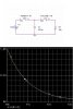
What are some Discharging effects? i know diodes and capacitors can produces some discharging waveform effects what are some networks or waveforms that can be done with discharging?

How does a network or circuit discharge?

How looking at AC polarity flips how do u look at at circuit at a discharging way?
 
What are Discharge Paths? and how would i know where one is?

Where are Discharge paths most common at?

What are Discharge waveform Curves?

what are Discharge Timing? how are the discharge timing made up ?
(using capacitors,resistors,diodes,transistors)
 
Im not sure what exactly you are asking but if you want to work out the discharge waveforms, the way i first learned them was through solving the 2nd order differential equations for the circuit. The Equation for current will plot the exact discharge waveform which will be a simple exponential in the case of a capacitor/resistor network. If you're using a diode, just remember when reversed biassed it clamps the output from going below -0.7v so in most cases u usually get the characteristic -negative spike down to -0.7v and thats why that is. Hope it helps.

Megamox
 
If its a capacitor and resistor in series :

INPUT------| | ---X---- /\/\/\/\/\------ GROUND

If you consider point X the discharge will look like an exponential decay. But this is only the case if the circuit is given time to discharge, if the input is continual and its frequency is faster than the time taken for any disharge you will not get any discharge because the input is continually charging up the capacitor before it gets time to discharge.

Megamox
 
Thanks for the information


discharge will look like an exponential decay

But what will a circuit discharge to ?

when reading a schematic how do u know where the Dischange Points are? where are the exponential decays dischanging to? when reading a schematic of a network or circuit?

How to measure the Dischange time?
 
For resistive circuits, the capacitor will discharge current into anything and everything it's connected to. Unfortuanantly beyond basic resistive loads, the exact discharge waveform is tough to calculate without a pen, paper, and a ton of free time on your hands.

Generally tough, you can summarize how things will look if the capcitor is discharging into a resistance by this:

V(t) = Vinitial*e^(-t/R*C)

Were V(t) is the capacitor's soon-to-decay voltage, Vinitial is the capacitors' last voltage before it started discharging, t is your time in seconds. Multiplying R with C before-hand will tell you how many seconds it takes to discharge the capacitor to about 33% of its original voltage. In theory, it never fully discharges.
 
Thanks for the information

decay voltage or dischange voltage does it look like a Fall time?

So capacitors and inductors are the only discharging components?

When does a Capacitor or inductor start to dischange? when the AC polaritys switch? or with the voltage or current is shut off with a switch?

If a Transistor or Tube thats be charged with voltage or current can't a Tube or Transitor Dischange into the Load or dischange back to the Input?
 
Yes, capacitors, inductors (and of course batteries) are the only energy-storing elements. Here's a PSpice simulation of what happens if you discharge a 100uF capacitor into a 10kOhm resistor after it's been charged with a 1 volt battery for 10 seconds. The switch on the left opens at the same time the switch on the right closes...

...so basically, you can see the voltage on the capacitor decaying to about 33% (looks a little more like 36% to me, but close enough) after exactly R*C (or 1 second).

Capacitors always fight any changes in voltage, while inductors fight any changes in current. So as soon as the 1-volt supply voltage disappeared because of the switches activating, it started discharging.

Generally speaking transistors and tubes do not store energy, and neither discharge nor charge. This isn't 100% accuracte because they do have unintentional capacitances, but these typically run in the range of nano, pico, or femto Farads and can be forgotten for basic circuits.
 

Attachments

  • discharge.jpg
    discharge.jpg
    41.4 KB · Views: 1,146
Thanks alot for the picture and information

I thought if u change the Plate of a tube and the AC polarity input changes the Plate dischanges

When looking at a Schematic of a Power supply or Preamp or Power amp how and where are the Dischanging Points around at? do i just look for Capacitors and inductors and see what Loads they are hooked up to ? or is there more and other "discharging Paths"? how do i find the discharing paths in a schematic where should i start or look for?
 
Honestly, they don't teach us much about about tubes anymore and I can't find any of my texts on them. If the capacitance between any two terminals of a tube is sufficiently high enough, there will be a slight discharge, but it should be very small.

Finding the path for a discharge in a amplifier is a very long and drawn-out process that requires doing 1st or 2nd-order derivatives, or a CAD simulator like PSpice. Generally though, you can "snapshot" where the energy will discharge to by replacing the capacitor in the schematic with a battery--just to keep things in perspective.

To find out how just the capacitor is affected, we just summarize the rest of the circuit as one big resistor, capacitor, inductor, and (sometimes) voltage source. This is how people are able to design home appliances without needing a schematic of the whole power grid.
 
What affects the Discharge Time?

Because the Discharge graph is Volts VS time(seconds)

So what would make the discharge time short?
What would make the discharge time Long or very long to discharge?

More capacitance or More inductance would store more energy but also
dischrage more
 
The discharge time will be large for large capacitances and/or high-resistance loads. If you want a fast discharge, you need to reduce the load as much as as possible. There is also an internal resistance called ESR that can cause a capacitor to discharge slowly.

Your energy (in joules) in the capacitor is: E = 0.5*(C*V²). Because of the V², we coilgun guys tend to favor high-voltage capacitors over high-capacitance types--usually. A similar case applies for inductors, where you have E= 0.5*(L*I²).
 
Thanks DigiTan for the help

is the RC or LC or RLC time constants (TP) be equal to the discharge time?
Or does the Discharge time slower or longer than the Time constant

In a Recifier tube or Recifier diodes there is a Passing path on half the cycle but the other half of the cycle is discharging

The Ripple in the power supple is the Time constants of the Filter caps but also the Discharge time thats why there is ripple and not a steady DC voltage

Ripple=time constant=discharge time ? does this sound right?
 
walters said:
is the RC or LC or RLC time constants (TP) be equal to the discharge time?
Or does the Discharge time slower or longer than the Time constant
Ah, that one's a great question! For RC and LC circuits, those time constants will always tell you how long it takes for the discharge to fall to 33%. For RLC circuits, the time constants get a lot more convoluted, and the discharge will cause a the circuit to "ring" at a certain frequency that's equal to 1/√(L*C). This time constant I'm not certain about [maybe another member can fill me on that].

Diodes are a lot more like voltage-controlled resistors. Ideally, their resistance will be almost zero anytime their anode is at a higher voltage than the cathode. Otherwise, that voltage will only open a "gap" in the diode's center that prevents charge carriers from crossing to the opposite side. That makes the diode act like a very large resistor (in the millions or billions of Ω's). It's also acts as a very small capacitor when it's reversed (in the pico-Farads, I think), which can affect high-speed operations.

Your 3rd paragraph is dead-on! The higher RC time constants will produce less ripple, so a high-powered load like a PC or stereo would need larger filter capacitors than something small like an alarm clock.
 
Thanks again for the help

What is good discharging VS bad Discharging?

Why would discharging be good? why would discharging be bad?

Diodes Block Discharging paths mostly?
most diodes don't discharge they are not storage components so they block discharging voltages coming the other way

99%-33% discharging voltage VS time(seconds) looks like a exp. curve
is there any way to get different Discharging Curves like a linear, like a high pass or low pass filter curves how it rounds off instead of just a exp. discharging voltage curves?

Does the Load make a big difference of the way the Discharging Curve looks like?
 
Generally, I'd consider a discharge "good" as long as it doesn't push the voltage/current limits of the circuit--or the capacitor itself. The slow, constant discharging due to ESR can be a bad thing for energy storage equipment like photoflash cameras and DRAM.

Diodes are a good way to block discharges. This is common practice with relay circuits, since the relay coil acts as an inductor and creates a backward voltage spike that tends to destroy logic devices. We can use a diode to "clamp" this backward spike and protect the transisors, chips, and other gizmos that might've been damaged.

The only case I can think of where a discharge would be linear is if the load resistance decreased by R(t) = e^-t. Even then, it's not exactly linear and my log math needs some work.

The load always has direct control over the discharge curve. Constant loads result in exponential decays, and a discharge that creates an LRC circuit will result in an oscillation. Also, in the case where a capacitor is discharged into another capacitor (with a resistor in parallel), the voltage on both first drops to (original capacitance/total new capacitance)*Original Vc, then decays exponentially using the new RC time contant. That one trips people up all the time.
 
Thanks alot for the help on this

where a capacitor is discharged into another capacitor (with a resistor in parallel), the voltage on both first drops to (original capacitance/total new capacitance)*Original Vc, then decays exponentially using the new RC time contant. That one trips people up all the time.

Is that like a power supply filtering section i see Capacitors in stereo,guitar amps in the power supply some capacitors are in parrallel and others are in series or both parallel/series capacitors discharging into another capacitors what happen here?
 
Status
Not open for further replies.

New Articles From Microcontroller Tips

Back
Top