Continue to Site

Welcome to our site!

Electro Tech is an online community (with over 170,000 members) who enjoy talking about and building electronic circuits, projects and gadgets. To participate you need to register. Registration is free. Click here to register now.

  • Welcome to our site! Electro Tech is an online community (with over 170,000 members) who enjoy talking about and building electronic circuits, projects and gadgets. To participate you need to register. Registration is free. Click here to register now.

Diode Bridge Rectifier Verification

Status
Not open for further replies.

givknow dge

New Member
upload_2015-4-4_19-20-8.jpeg

Hello
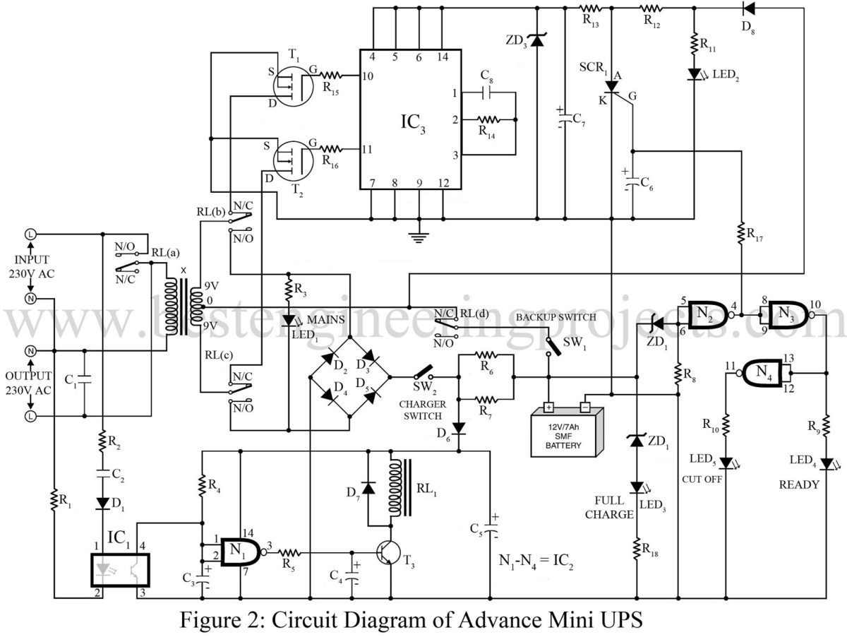
I am trying to verify the diode circuit labelled "Diode Bridge Rectifier" above. Diagrammatically, it can also be represented as:
2000px-Diode_bridge_alt_2.svg.png

On placing the positive terminal of my voltmeter (switched to diode mode) on one of the AC terminals and the negative on the other I get a reading of 0.130 V. When I swap the terminal positions, the same reading repeats. Is it safe to conclude the bridge is broken? My google search say the reading should be OL. But verification from this forum would be helpful.
 
Last edited:
Your schematic of a diode bridge is correct.

When testing the diodes, you will almost certainly get some odd results while they are still connected in circuit.
I suggest that you disconnect one end of each diode and repeat the test.

I would expect that you get a reading of 0.6 to 0.7v with the meter probes one way round on the diode, and OL with to probes the other way round.

JimB
 
Are you testing an isolated, unconnected bridge with an Ohmmeter? Or is it still connected to the power supply?
 
Certainly odd readings. Do as JimB suggests and try again.

What were the operation symptoms of the board you posted?
 
I've tried JimB's suggestion and the diodes seem fine as well as the bridge when disconnected from the rest of the circuit.

But the DC output of the bridge comes at 0V when the circuit is active.

The operation symptoms of the board are that it is basically the battery charger module of an un-interruptable power supply (UPS). When

power is available at the A.C mains, the circuit starts charging the battery. When power fails, it stops.


However, there was a sudden voltage surge at the AC mains and the UPS has not been functioning properly ever since. It is not able to

detect power at the AC mains and keeps supplying power from its batteries.


Thanks for the feedback. Any suggestions on further debugging the circuit would be quite helpful. Also, clicking on the small image at the top enlarges it thus giving a detailed view of the actual circuit.
 
OK, it is difficulty to tell from the picture, but the whole of the equipment looks very dusty and dirty.
Cleaner is always better.
Brush off the loose dust with a 1" paint brush, use a vacuum cleaner to suck up the dust as you brush.

What about the other diode bridge, near the transformer? Hve you tested that?

What about the capacitor, the big blue one with the cross on top?
It looks slightly "bellied out". Worth trying a replacement.

JimB

Editing with further thoughts:

Turn the board over and examine the solder joints.
Pay particular attention to:
The two white wires from the big transformer.
The pins on the little transformer.
The pins on the two large transistors.

All of these are prime candidates for the wire breaking free from the solder.

JimB
 
Last edited:
I've verified the following:
white wires from the big transformer
Pins on the little transformer
Pins on the two large transistors

Replacing the capacitor without being sure its faulty is not an option at the moment.
The other diode bridge is working fine giving the appropriate DC output.
 
This bridge verification is actually part of the process of determining which section of the UPS is responsible for power sensing
at the mains as I am assuming that section has broken down thus preventing the UPS from detecting AC mains. However, I could
be wrong and it could be that the bridge would work once it gets a control signal from some other circuit. To cater to that possibility,
I've pasted below the three main circuits of the UPS: Main board, Battery charger and Over-load protector.
upload_2015-4-6_0-25-40.jpeg

upload_2015-4-6_0-26-32.jpeg

upload_2015-4-6_0-26-32.jpeg


Someone with familiarity of UPS circuits would know how the control flow and that which circuits together determine if the UPS should switch
to backup or the mains supply. It would be of immense help if that circuit along with the possible issues due to a voltage surge could be pointed out.
 

Attachments

  • upload_2015-4-6_0-26-50.jpeg
    upload_2015-4-6_0-26-50.jpeg
    344.2 KB · Views: 404
Someone with familiarity of UPS circuits would know how the control flow and that which circuits together determine if the UPS should switch
to backup or the mains supply. It would be of immense help if that circuit along with the possible issues due to a voltage surge could be pointed out.
Sort of flying blind here. Maybe a member recognizes the boards, but until that happens, please give us your UPS Brand/Model. Not all UPS units use the same circuit(s).

Many UPS units, especially older ones (which yours appears to be) have schematics available on the net, which would make troubleshooting a much easier task.
 
One cannot expect DC behaviour of a bridge diode set while in-circuit with inductive transformers with low DCR and with some load impedance.

There are several bridges , so I don't know why just one is singled out for this simple discussion.

upload_2015-4-5_20-47-29.png
 
cowboybob:
It is indeed old and I can not figure out its brand/model. The casing doesnt seem original and only reads the name of the guy I purchased it from. Its as if the guy copied the design from some brand and customized it into his own.
Given this situation, would you have any pointers on how to proceed?

tony stewart:
That is a good question. Since the UPS has stopped sensing power at the AC mains, I am looking for the circuit that performs this sensing. Usually such circuits make use of an opto-coupler and in this case, only the battery charger circuit has one (the white rectangular IC on the extreme bottom left in the image above). My assumption is that some thing has gone wrong in this circuit and is preventing the opto-coupler from working. Hence it is the bridges in this circuit and specifically the one feeding the opto-coupler that are being singled out. BUT, I have no reason to be sure that my assumption is correct and I am looking for someone to verify/contradict it.


Thanks guys
 
optos would be used for inverter feedback, primary isolation is transfo.

You will have to measure DC and AC voltage with respect to ground and on big caps to check the circuit... starting from Line input.

230Vac line will be converted to 550Vdc or so then bucked down to charge battery etc...

It takes a clean 1 mm gap to arc 500V but 3mm is safe unless it is dirty and moist.
 
Last edited:
Thanks Nigel, haven't had coffee yet this morning.. Here they like to keep revenue up by running at ~125~128V, we have pretty reliable power except when road salt and water freeze in underground old wiring.


givknow dge... unless you know how to design something, thus reverse engineer it easily, or have test experience like a TV repair guy... its' pretty hard to debug with an ohm meter unless it is basic fuses, dry caps or burnt parts.

... so clean off the boards with some compressed air can spray a bit or just poke with (-) permanently clipped to gnd with one hand away to record levels. and other hand to probe.

AC will read DC at twice the level on cheap meters.
 
This is not, obviously your UPS (since it's the whole UPS, not just the charger circuit), , but it's a start:
circuit-diagram-of-advance-mini-ups.jpg

NOTE! Lethal voltages present. Take all necessary precautions.

With NO POWER applied to the board(s), I would start by carefully wiping off the tops of the ICs and the transformer (which seems to have a circuit displayed on it) on the board you showed in post #10. Let us know whatever numbers that are displayed, as this will help with the troubleshooting. I'm approaching this from the assumption that one or more of the solid state devices (bridge diodes, opto-coupler or IC chip) was fried by the surge. Could, of course, be something else, but got to start somewhere...

With the board powered up, confirm absence/presence of AC voltage (and what that value is) at the output of the transformer. Then confirm that AC level is at the appropriate diode junctions of the bridge (presumably those 4 diodes closest to the transformer - check the traces under the board for connections to the transformer). If present, check the other two junctions for a DC level and its value.

If no DC, replace all diodes. Note that they may blow again at power up due to some downstream problem, but diodes are cheap.

If DC is present, stop, power down and we'll continue with the troubleshooting.
 
coyboybob:
I'll work on your suggestions and post the result

Tony Stewart and Nigel Goodwin, thanks for your input. Though I don't get
optos would be used for inverter feedback, primary isolation is transfo.

How is the inverter feedback being routed to the opto here? I was under the impression that the opto-coupler was being used in a situation similar to the one shown in cowboybob's UPS circuit.


Thanks
giv know
 
A PIC was the last thing I expected to see but, then, I am no UPS expert. I can see how an 8 channel ADC uC could be useful though.

Anyway, givknow dge, let's check, with the board powered up, the voltage levels (if any) at the two ICs in the snip below: (would expect to see 2.0 to 5.5VDC on the PIC and perhaps ≈3VDC across the two on the opto-coupler. Other pins on the opto-coupler MAY BE LETHAL.
upload_2015-4-7_17-46-33.png

Without any idea of the traces layout, we're flying by the seats of our pants now. Just trying to chase down where the DC is going or is lost.

Just out of curiosity, have you ever tried to "reverse engineer" (match copper traces to components) a PCB before? It is not easy, but it would help considerably with the trouble shooting.
 
Status
Not open for further replies.

Latest threads

New Articles From Microcontroller Tips

Back
Top