Electro Tech is an online community (with over 170,000 members) who enjoy talking about and building electronic circuits, projects and gadgets. To participate you need to register. Registration is free. Click here to register now.
Welcome to our site! Electro Tech is an online community (with over 170,000 members) who enjoy talking about and building electronic circuits, projects and gadgets. To participate you need to register. Registration is free. Click here to register now.
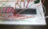
Your wiring looks alot better.
Can you check the power to the chip?
Pin 1 is positive and pin 26 should be negative.
Seems that chip needs 5 volts or more supply voltage.
You may need more than 4.5 volts to get it to work!!!
Your wiring looks alot better.
Can you check the power to the chip?
Pin 1 is positive and pin 26 should be negative.
Seems that chip needs 5 volts or more supply voltage.
You may need more than 4.5 volts to get it to work!!!
remon7, I was asking for two lists: One of the components you used, and one of the components specified by the schematic. You gave me the one of the components you used, but not of the ones required by the schematic. Or am I missing something?
remon7, I was asking for two lists: One of the components you used, and one of the components specified by the schematic. You gave me the one of the components you used, but not of the ones required by the schematic. Or am I missing something?
remon7, I was asking for two lists: One of the components you used, and one of the components specified by the schematic. You gave me the one of the components you used, but not of the ones required by the schematic. Or am I missing something?
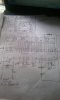
I gave you right list where i mentioned which i used and which are not. with name and quantity ....
1x - 220 Ohm Resistor
1x - 10K Resistor
1x - 15K Resistor
1x - 47K Resistor
1x - 100K Resistor
1x - 1M Resistor
1x 10K Pot
1x - 100pF Capacitor <<<< I am using 101K it looks like green tablet. <<<<Look this notes <<<<
1x - 10n Capacitor<<<< I am using 103J it looks like green rectangular tablet.<<<<Look this notes <<<<
1x - 100n Capacitor<<<<I am using 104K it looks like Yellow rectangular tablet<<<<Look this notes <<<<
1x - 220n Capacitor<<I am using 224J it looks like Yellow rectangular tablet<<<<Look this notes <<<<
1x - 470n Capacitor<<I am using 474J it looks like Gray rectangular tablet<<<<Look this notes <<<<
2x - 10uF Capacitor <<<<<I am using 10uf volts 63volts 2 piece and 1 piece 10uf 16volt. <<<just use 2 piece.<<<<Look this notes <<<<
3x - 1N4148 Diode
1x - ICL7107 IC
1x - 7660 IC
2x - MAN6910 2-digit LED 7-segment Display
Ah, my apologies remon7. I did not realize you had combined the two lists. At first glance all the components you used should work. Make sure you fix the voltage issue that 4pyros pointed out though. It won't work if you don't supply the -5v in the right place.
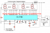
In the Schematic you put on Post #42, the 10uF Capacitor between Pins 5 & 3/Gnd, is in BACKWARDS.
The Positive of this Cap should go to pin 3/Gnd.
The Negative of this cap should go to Pin 5.
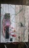
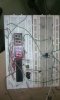
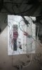
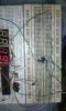
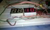
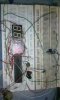
its amazing maybe its working well. To be honest when i am working on this project that's time i was thinking that many people(Engineer )<DerStrom8, chemelec, 4pyros>with me. helping me about advice, planning, ideas. That's why i did not lose my hope. Rather its increased after reading your messages. Look my digital voltmeter >>
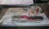
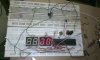
unfortunately its not work well maybe its on right track..Need more Help ....yeah Derstrom8 i used -5 part with 5volt supply negative part and positive +5volt positive end and ground still ground there is no charge . u noticed that in this video first LED Display was off i dont know even when i connected for measuring volts then first LED just on showing me number 1 digit. just it...so tell me next procedure ....
Input means measuring voltage is 3volt maybe .......again at home i used 4.5volt for supply but ic wants 5volts. usually in campus lab i used 5volts from power supply ....But its working great at home means in 4.5volts...
Thanks
>>>>>It includes a 3.5-digit LED display with a negative voltage indicator. It measures DC voltages from 0 to 199.9V with a resolution of 0.1V. The voltmeter is based on single ICL7107 chip and may be fitted on a small 3cm x 7cm printed circuit board. The circuit should be supplied with a 5V voltage supply and consumes only around 25mA.<<<<<< please look this website i followed this website ideas >>>https://projectlistinfo.blogspot.com/2013/01/how-to-make-digital-voltmeter.html it says 0 to 199volts.
This site uses cookies to help personalise content, tailor your experience and to keep you logged in if you register.
By continuing to use this site, you are consenting to our use of cookies.