Electro Tech is an online community (with over 170,000 members) who enjoy talking about and building electronic circuits, projects and gadgets. To participate you need to register. Registration is free. Click here to register now.
Welcome to our site! Electro Tech is an online community (with over 170,000 members) who enjoy talking about and building electronic circuits, projects and gadgets. To participate you need to register. Registration is free. Click here to register now.
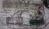
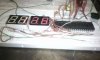
Looking at your pictures of the Led Displays, It Definately looks like your connections to the Led's are NOT correctly connected.
If they were Correct, you would get PROPER Numbers Showing.
Maybe your Counting the Pins in a Reverse direction of what they should be?
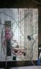
remon, why do you refuse to answer my questions? For the last time, please tell us EXACTLY what parts you're using, and compare it to what you're supposed to be using. In other words, give us two parts lists--the original, which you SHOULD be using, and the list of parts that you are ACTUALLY using. And again, please neaten up your wiring!
If you continue to refuse to answer these questions, then I will refuse to answer yours. I can't help you if you don't give me all the information I need.
Hi DerStrom8!! Actually i tried to represent my problem....Basically i am using these components.....
1x - 220 Ohm Resistor
1x - 10K Resistor
1x - 15K Resistor
1x - 47K Resistor
1x - 100K Resistor
1x - 1M Resistor
1x 10K Pot
1x - 100pF Capacitor <<<< I am using 101K it looks like green tablet.
1x - 10n Capacitor<<<< I am using 103J it looks like green rectangular tablet.
1x - 100n Capacitor<<<<I am using 104K it looks like Yellow rectangular tablet
1x - 220n Capacitor<<I am using 224J it looks like Yellow rectangular tablet
1x - 470n Capacitor<<I am using 474J it looks like Gray rectangular tablet
2x - 10uF Capacitor <<<<<I am using 10uf volts 63volts 2 piece and 1 piece 10uf 16volt. <<<just use 2 piece.
3x - 1N4148 Diode
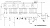
1x - ICL7107 IC
1x - 7660 IC
2x - MAN6910 2-digit LED 7-segment Display
Its common here i tried to find real name(quantity/quality but i could not get thease same things/ whatever shop keepers told me, it will work same function thats u want to do .)
Thank you for the parts list, remon7. Now could you post the parts list for the schematic you're following? Use the same format as the above post, if possible.
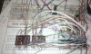
Also, have you tried neatening up your wiring yet?
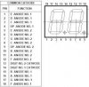
Just now i have checked my seven segment display maybe i got faulty here. can u tell me how could i check 7 segment display? i used common annod and common cathod method.. in 1.5v
Just now i have checked my seven segment display maybe i got faulty here. can u tell me how could i check 7 segment display? i used common annod and common cathod method.. in 1.5v
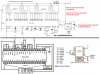
Note that the PINS are labeled a bottom view. It would follow the normal IC convention that pin #1 is on the lower left in the orientation that you can read them.
You can test them with your DMM on the diode scale, just like you would test a normal diode. The voltages will be higher, though. Like LED's.
So with 10 mA, you would need R <= (5-2.5)/0.010 Ohms in series with your 5V supply. Place this resistor in series with the 5V supply and place on the Anode,
Connect each segment to ground. The appropriate segment should light.
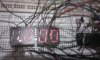
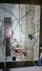
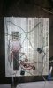
Hi all, its 5volts circuit but i am using 4.5volts. but its quite looking good and also display turn on. also i have attached some pictures. one picture about 7segment display, just i tried to follow this 7segment display rule...... i have noticed if i use any battery for volts checking its still remain same result not change in output....
Thanks
Your wiring looks alot better.
Can you check the power to the chip?
Pin 1 is positive and pin 26 should be negative.
Seems that chip needs 5 volts or more supply voltage.
You may need more than 4.5 volts to get it to work!!!
Hi DerStrom8!! Actually i tried to represent my problem....Basically i am using these components.....
1x - 220 Ohm Resistor
1x - 10K Resistor
1x - 15K Resistor
1x - 47K Resistor
1x - 100K Resistor
1x - 1M Resistor
1x 10K Pot
1x - 100pF Capacitor <<<< I am using 101K it looks like green tablet.
1x - 10n Capacitor<<<< I am using 103J it looks like green rectangular tablet.
1x - 100n Capacitor<<<<I am using 104K it looks like Yellow rectangular tablet
1x - 220n Capacitor<<I am using 224J it looks like Yellow rectangular tablet
1x - 470n Capacitor<<I am using 474J it looks like Gray rectangular tablet
2x - 10uF Capacitor <<<<<I am using 10uf volts 63volts 2 piece and 1 piece 10uf 16volt. <<<just use 2 piece.
3x - 1N4148 Diode
1x - ICL7107 IC
1x - 7660 IC
2x - MAN6910 2-digit LED 7-segment Display
This site uses cookies to help personalise content, tailor your experience and to keep you logged in if you register.
By continuing to use this site, you are consenting to our use of cookies.
 .
.