Continue to Site

Welcome to our site!

Electro Tech is an online community (with over 170,000 members) who enjoy talking about and building electronic circuits, projects and gadgets. To participate you need to register. Registration is free. Click here to register now.

  • Welcome to our site! Electro Tech is an online community (with over 170,000 members) who enjoy talking about and building electronic circuits, projects and gadgets. To participate you need to register. Registration is free. Click here to register now.

digital speedometer using AT90S2313

Status
Not open for further replies.
fever said:
i heard that AT90s2313 contain 2 fuses where as ATTiny2313 has lot of fuses.

Not a lot, only 17 fueses! :)

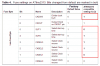
They are inside three bytes called Low/High/Extended fuse byte. However, the ATTiny2313 designer has already taken care of the user wanting to change to Tiny2313 by providing a table of fuse setting to be used.

The table is inside a migration document here:

AVR091: Replacing AT90S2313 by ATtiny2313

and also posted here for you with changes marked in red. Only the low fuse byte is shown as default factory values are used in both High/Extended fuse bytes and doesn't need any change.
 

Attachments

  • 2313.png
    2313.png
    8.8 KB · Views: 549
I have a brief look at the link you posted.

The clock selection in the webpage is "crystal, 8MHz or higher" while in the table by ATMEL is "crystal, 3-8MHz".

If in doubt, check the AVR2313 datasheet page 26 doc2543.pdf.
 
speedometer query pls help

pls do tell me tat using this microcontroller can we get a combined instrument that can measure speed as well as distance simultaneously or one at a time. pls do reply electronics gurus:p
 
Of course it can. Please refer back to page one of this thread.

The instrument measures both distance(how many turns of wheel x wheel circumference) and time taken, and then it works out the speed.

Using the number of turns of the wheel from start to finish, you can work out the total distance travelled.
 
can u suply me the source code that has to be put to the microcontroller memory and it can be operated as a dual instrument measuring speed and distance
 
Sorry I can't. I'm not the author of this instrument.

If you refer to the original edn.com link in page1, the authur has provided the source code file for download.
 
ya thanks buddy i got the code but tell me will tat code work as spedometer cum distance meter simultaneously. do i have to modify something in tat code or directly burn it into the microcontroller. pls help. if u cant tell ere pls message me. i need it urgently
 
yes u have to modify the radius of the wheel.
if u open the .asm file in notepad u'll find the details
 
halleffect sensor

can i use hall effect sesor of HONEYWELL in place of allegro as i m not getting it. its no is HI300
 
Last edited:
may be u can try.any 3 legged hall-sensor work here i think (iam not sure as i don't have one)
@lenniegonzales
please go to 1st page,ther u'll find the link.and if u go through all the posts in this thread u'll know abt the code modification etc....
 
Hi mate, I made a fully Digital dash and there is many ways you can go about this.

Im coming from a BASIC STAMP Point of view here (Dont Laugh)

Here is the main parts list:
LM2917 'Frequency to Voltage Convertor'
ADC
Stamp
LCD
Hall Effect

The hall effect sensor was connected to the LM2917, which was configured to give 1v/60Hz, this was then measured by the ADC and shifted into the stamp.

I dont know how the AVR works but the stamp could only measure pulses shorter than half a second, which meant it wouldnt read when the car was goingbelow say 20mph. It also meant I could get the stamp measuring other data and instead of couting pulses. HTH Lee

ADC
 
pls help me again

electronics gurus
i have made the speedometer but the distance is not getting reset whenever i grnd pin no 1 . the last value remains there. also wen the crt is turned on the and wheel is roated it gives the speed but if the wheel is stationary for some time and again moved there is no reading. i have to power off then on to get it back to normal function. pls do tell me tat is my crt working properly or some rectification is needeed pls do reply
 
i am also planning on building the speedo, i had a look at the diagram, but some capacitors look like they are greencaps (or ones like them), most of them are 0.1 to 10 uF and higher, but i can't tell if those ones are electrolytic or not. can someone please put them in a list an me what type the are (like c1: c2:, etc)?

thanks
 
Status
Not open for further replies.

Latest threads

Back
Top