Continue to Site

Welcome to our site!

Electro Tech is an online community (with over 170,000 members) who enjoy talking about and building electronic circuits, projects and gadgets. To participate you need to register. Registration is free. Click here to register now.

  • Welcome to our site! Electro Tech is an online community (with over 170,000 members) who enjoy talking about and building electronic circuits, projects and gadgets. To participate you need to register. Registration is free. Click here to register now.

Digital Fuel Meter (LED type gauge) - Need Help!

Status
Not open for further replies.
I can't seem to make my project work the way I want it to. Im using an LM3914 IC for the LED Bar gauge. Please help me... Here are the points of my project:

1.) My motorcycle is running on 12Volts
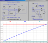
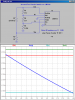
2.) The fuel sender have 2 wires and only 1 wire goes to the analog gauge (Resistance: 100 Ohms empty & 8 Ohms full).
3.) The circuit I used was the one on the Datasheet (Page 11). I used variable resistors for adjustments and calibration.
4.) I cannot determine the voltage from the sender because it reads 12v being it as a ground. But testing it disconnected reads the resistance range mentioned in #2.
5.) The senders output has a smooth resistance variation (e.g. Potentiometer type I guess)

Can anyone give me an idea on what resistor combination to use or a schematic that will make the above given values function? Do I need to step down the voltage? Do I need a regulator?

I badly need help on this.

@12v power, the gauge should light full on full tank (8 Ohms) and no lights at empty (100 Ohms).

Thanks and more power.

P.S. I'm good at PIC's (a programmer by nature) but not on this traditional circuit logic.
 
Last edited:
Are you trying to use the bargraph as a replacement for the OEM gauge, or are you attempting to hook it into the OEM gauge system in a way that the OEM gauge works normally?
 
HI Mike, thanks for the replies. I'm trying to replace the OEM gauge. So the 3 wires that goes to the OEM gauge connects directly on my planned digital fuel meter discarding the OEM.
 
Hi mike, seems that my posts are still under moderation.

Yes i'm trying to use the bargraph to replace the OEM gauge.

Hope someone could help me on this.
 
Here is a hack that progressively lights LEDs on a LM3914 as the sender resistance goes from 15Ω to 145Ω. Unfortunately you probably want it to go the other way because you want all the LEDs lit when the tank is full, not empty. This is a partial schematic only; you will have to look up the data sheet for the LM3914 and hook up the other pins as shown there.

I use the LM3914's internal voltage regulator to create a bridge where the internal comparator voltage divider's Rhi and Rlo are connected to voltages that just straddle the range of Sig. Look at the plot and see how V(sig) ranges from slightly below V(lo) to slightly above V(hi) as the sender resistance changes. The current out of the RefOut pin sets the LED brightness. With these resistor values, the LED current will be about 20mA

To invert the way the LEDs light, it will require the addition of an opamp, or if the sender has two isolated connections (meaning that one end of the sender in not intrinsically grounded to the gas tank), it might be possible to flip the bridge circuitry upside down and do it without adding the opamp?
Please advise.
 

Attachments

  • FuelCycle.png
    FuelCycle.png
    52.6 KB · Views: 1,495
Last edited:
This is the inverted version which will work if both ends of the sender are isolated from the grounded fuel tank.
 

Attachments

  • FuelCyclei.png
    FuelCyclei.png
    32.5 KB · Views: 2,063
I don't have an LM3914, so this is untried....

Can you reverse the operation of the comparators by swapping Rlo and Rhi?
 
4.) I cannot determine the voltage from the sender because it reads 12v being it as a ground. But testing it disconnected reads the resistance range mentioned in #2.

hi bb,:)
I have read the posts in the thread, but I am not sure what the above comment means, can you give more details.?
I assume that the cycle frame is connected to the negative end of the battery.??

When you measure the full tank (15 Ohms) and no lights at empty (145 Ohms). how are you connecting the ohm meter, for example is one meter probe to the cycle chassis/frame and the other probe to the 'free' end of the sender wire.??
 
Eric, sounds like another job for your cool LM3915 program...:)
 
hi bb,
Look at this circuit as an option, the LM3914 image shows a half full tank.
 

Attachments

  • HowFG2.gif
    HowFG2.gif
    22.9 KB · Views: 1,022
  • HowFG2x.gif
    HowFG2x.gif
    16.4 KB · Views: 1,222
Hello,

Thank you so much for the help and replies.

I edited my starting post because I realized that my multi-tester's readings have discrepancy, low battery :(.

My actual sender resistance readings are 10 Ohms full and 100 Ohms empty.

@Mike thank you for the sample schematic. Finally I realized the reason why I wasn't able to make it work on my own. I've been connecting the sender out wire directly on pin 5 of LM3914 and not as a part of the voltage divider resistance.

@ericgibbs When I tried measuring the voltage through the fuel sender, I dumbly connected the (-) lead of the tester to the sender out, while connecting the (+) lead of the tester on the OEM gauge's (+) wire. So obviously it will always read at around 12v. Thank you also for the schematic sir.

I'll try first eric's schematic because it already inverts the output of the sender (Full bar leads on 10 Ohms and none at 100 Ohms. Should the resistors' values needed changing? As my sender fuel readings have changed?
 
hi,
Replied to your PM, I dont understand why that your posts are being held for so long in moderation,?
I will re-look at the circuit for the new sender values you have PM'd, ie: 10R to 100R.
To confirm what the LTspice is showing I will build the actual circuit and post tomorrow.
 
I'll check tomorrow then. My breadboard is ready here :D.
hi bb,
Look at the images for this option.
The CA3240 or equivalent specification, is a OPA is a 8 pin dual.
The 7808 is a standard voltage regulator, its needed because of the changes in the cycle battery voltage line.
The plot shows that its linear within 1 or 2%
 

Attachments

  • FG2LMa.gif
    FG2LMa.gif
    16.4 KB · Views: 2,006
  • FuelGauge2.gif
    FuelGauge2.gif
    29.9 KB · Views: 1,314
  • VoPlot1.gif
    VoPlot1.gif
    9.2 KB · Views: 549
hi eric,

What you did is amazing and I can't wait to try it out. I just want to clarify a few points on the schematic.

1. Can I use the TL072 Dual-OpA? I have a bunch lying around as I am also DIYing guitar gadgets.
**broken link removed**

2. Should the +vr be connected to the regulated output of the 7808 which is 8v?

3. V1 is the 7808, U1 is the CA3240 then what is U2?

4. Does the Vo1 (the cut line part) points to nowhere?

5. Are the R4 and R8 variable resistors? Can I use trim pots using only its 2 pins?
 
Last edited:
hi bb,
Look at this circuit as an option, the LM3914 image shows a half full tank.

Hi Eric,

Thats really nice work. Is this your VB program? How to get a copy of it ( if possible ) ?:D
 
Hi Eric,

Thats really nice work. Is this your VB program? How to get a copy of it ( if possible ) ?:D
hi aljamri,
It is VB5, the exe file is on my Forum Blog.

[urlhttps://www.electro-tech-online.com/blogs/ericgibbs/136-single-dual-lm3914-v3-0-calculator.html[/url]
 
Last edited by a moderator:
hi eric,

What you did is amazing and I can't wait to try it out. I just want to clarify a few points on the schematic.

1. Can I use the TL072 Dual-OpA? I have a bunch lying around as I am also DIYing guitar gadgets.

2. Should the +vr be connected to the regulated output of the 7808 which is 8v?
No, connect as shown to the junction of the two 470R's

3. V1 is the 7808, U1 is the CA3240 then what is U2?
U1 and U2 are the two parts of the same DUAL opa package

4. Does the Vo1 (the cut line part) points to nowhere?
The vo1 line is for SIM only

5. Are the R4 and R8 variable resistors? Can I use trim pots using only its 2 pins?
Yes, they are variable resistors, connect the centre pole [wiper] to one end of the pot with a wire link.

Hi bb,
I will look at the TL072 spec.

EDIT:
All the info on the datasheet referes to dual supply operation.?
Looking at the output stage of the TL072 suggests it will not get close to zero with a single supply voltage.

Others who have used this device with a single supply maybe able to confirm this.???
 
Last edited:
Hi eric,

I have built your awesome schematic except that CA3240 isn't available locally in my area. Do you have any alternatives to these Dual OPA? This is the only remaining problem and everything's good to go.

I will post results after everything has been tested to help other forumers.

Biboy
 
Hi eric,

I have built your awesome schematic except that CA3240 isn't available locally in my area. Do you have any alternatives to these Dual OPA? This is the only remaining problem and everything's good to go.


I will post results after everything has been tested to help other forumers.

Biboy
hi,
Can you buy say LM358, TC358, if not what can you get.?
 
Status
Not open for further replies.

Latest threads

Back
Top