MD MUBDIUL HASAN
Member
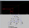
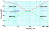
Can you show any circuit idea?The hearing graph I posted shows a loss of high frequencies of 12dB per octave for men at 55 to 65 years old.
12dB per octave is made with a second order highpass filter and the hearing cutoff frequency changes with age.
In which aspect you are saying 6dB? Kindly give any related documented to understand.Your tone controls circuit is a single order filter that produces only 6dB per octave and does not have an adjustable cutoff frequency. 6dB per octave is a small hearing impairment experienced by men 35 to 45 years old and they will not bother with a hearing aid for such a small amount.
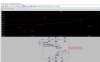
Sure, I wish to use ATmega128.If you want to make a hearing aid then make much more complicated circuit.
Yes, this option remains for MCU coding.You are making an analog circuit. Modern digital hearing aids have not used analog circuits for many years.