Electro Tech is an online community (with over 170,000 members) who enjoy talking about and building electronic circuits, projects and gadgets. To participate you need to register. Registration is free. Click here to register now.
Welcome to our site! Electro Tech is an online community (with over 170,000 members) who enjoy talking about and building electronic circuits, projects and gadgets. To participate you need to register. Registration is free. Click here to register now.
hi,
Q: I'm never use any 100nF bypass capacitors across the Vcc and gnd pins of the ICs. Does this affect the circuit?
Without the bypass/decoupling capacitors you will have problems caused by 'noise' on the power rails.
Always use decoupling, ideally one near each ic's +V and 0V pins.
Also have a 100uF near the point where you connect your incoming supply lines.
In one of your earlier posts you said you are using a 9Volt battery.
The circuit requires a +5 Volt supply to the ic's!!!, if you apply +9V you will damage your ic's.... Let me know.
Hi
Quote: i have put the capacitor and there is no led light up at all. I need to put the capacitor before the vcc and gnd, rite? You connect the decoupling capacitors from +5V to 0V [gnd]
yap...but my project stated i can use either use 9 volt bettery or using a voltage regulator n connect to dc adaptor Your TTL ic's are designed to operate using a +5Volt supply rail.
Either with a 9V battery or an dc adaptor you REQUIRE a +5Volt regulator.
thanks!any idea what's other problem could be?
If you give me clue what the problem is, I may be able to answer the question.
As Eric wrote, 9 Volt is too much for TTL ICs, they need 5 Volt.
So you may have damaged the ICs.
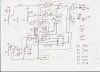
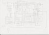
I suggest that you measure the voltages on U5/11. It should be high normally. Then press button B. Does the voltage at U5/11 go low briefly after the first clock pulse?
If not, measure the voltage on U6a/D. It should be high normally and go low when B is pressed. Then measure the voltage at U6a/Qa. It should be high normally and go low when B is pressed after a clock pulse.
Then measure the voltage on U6b/Qb. It should be high normally and go low when B is pressed after two clock pulses.
What is the oscillator frequency? It needs to be 1 Hz or less.
As Eric told you, you should connect 100 nF capacitors between pins 7 and 14 on U1, U2. U3, U4 & U6 and across pins 8 & 16 of U5 and a 100 uF acroos the supply line.
Connect a 5 Volt supply.
Does the circuit now work?
If not, turn the power off and remove ICs U4 & U5.
With switches S0 & S2 off, the green LED should blink at the oscillator rate.
If so, put a gnd on pin 12 of the U5 socket and the red LED should blink.
If so, leave the gnd on pin 12 and put a gnd on pin 6 of the U5 socket, switch s0 on and the red LED should blink.
If so, leave the gnd on pins 6 & 12 of the U5 socket, switch s2 on and the green LED should blink.
If so, turn the power off, remove the gnds from pins 6 & 12 and plug U5 in.
Switch the power on and see if U5 is counting.
If so, turn the power off and plug U4 in.
Turn the power on a see if the circuit works.
These tests should help you to locate where any faults are.
For example, if U3 is damaged, either the LEDs will not go on when they should or may be permanently on.
As Eric told you, you should connect 100 nF capacitors between pins 7 and 14 on U1, U2. U3, U4 & U6 and across pins 8 & 16 of U5 and a 100 uF acroos the supply line.[I never connect any capacitors as i got no capacitor now]
Connect a 5 Volt supply.
Does the circuit now work? [No]
If not, turn the power off and remove ICs U4 & U5.
With switches S0 & S2 off, the green LED should blink at the oscillator rate.
[Green Led Light up]
If so, put a gnd on pin 12 of the U5 socket and the red LED should blink.
[Green Led light up]
If so, leave the gnd on pin 12 and put a gnd on pin 6 of the U5 socket, switch s0 on and the red LED should blink. [Red led light up]
If so, leave the gnd on pins 6 & 12 of the U5 socket, switch s2 on and the green LED should blink. [Green Led light up]
If so, turn the power off, remove the gnds from pins 6 & 12 and plug U5 in.
Switch the power on and see if U5 is counting. [not counting]
If so, turn the power off and plug U4 in. [not counting]
Turn the power on a see if the circuit works.
These tests should help you to locate where any faults are.
For example, if U3 is damaged, either the LEDs will not go on when they should or may be permanently on.
Can advise which part that is having fault? Thanks a million!!
As Eric told you, you should connect 100 nF capacitors between pins 7 and 14 on U1, U2. U3, U4 & U6 and across pins 8 & 16 of U5 and a 100 uF acroos the supply line.[I never connect any capacitors as i got no capacitor now] This may be a problem when the counter is working. You should get some capacitors as soon as possible.
Connect a 5 Volt supply.
Does the circuit now work? [No]
If not, turn the power off and remove ICs U4 & U5.
With switches S0 & S2 off, the green LED should blink at the oscillator rate.
[Green Led Light up] Is the oscillator oscillating, if so at what frequency?
If so, put a gnd on pin 12 of the U5 socket and the red LED should blink.
[Green Led light up] Have you changed ICs U2 and U3, they may have been damaged by the 9 Volt?This is strange given the answers below. Do this again and measure the voltgae on the output of U1c, it should be high since U5/12 is low. If so, measure the other inputs to U2a and the output of U2a.
If so, leave the gnd on pin 12 and put a gnd on pin 6 of the U5 socket, switch S0 on and the red LED should blink. [Red led light up] Good. /COLOR]
If so, leave the gnd on pins 6 & 12 of the U5 socket, switch s2 on and the green LED should blink. [Green Led light up] Good. This together with your previous answer tends to indicate that U2 & U3 are OK
If so, turn the power off, remove the gnds from pins 6 & 12 and plug U5 in.
Switch the power on and see if U5 is counting. [not counting] It may be damaged, did you change it for another one?
If so, turn the power off and plug U4 in. [not counting]
Turn the power on a see if the circuit works.
These tests should help you to locate where any faults are.
For example, if U3 is damaged, either the LEDs will not go on when they should or may be permanently on.
Can advise which part that is having fault? Thanks a million!!
If so, put a gnd on pin 12 of the U5 socket and the red LED should blink.
[Green Led light up] Have you changed ICs U2 and U3, they may have been damaged by the 9 Volt? This is strange given the answers below. Do this again and measure the voltgae on the output of U1c, it should be high since U5/12 is low. If so, measure the other inputs to U2a and the output of U2a.
Pin 8 of 7400 is 4.4V and pin 8 of 7410 is 0.09V and pin 9 of 7410 is 1.47V.
Seem like U2a is damage, right?
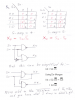
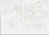
I have managed to change 74191, but the output still the same. did u see my redrawn ic pin layout, is there any connection wrong with the dip switch. And one thing about your kanaugh map, i was wondering how come you are using nad gate and not and gate?
I have managed to change 74191, but the output still the same. did u see my redrawn ic pin layout, is there any connection wrong with the dip switch. And one thing about your kanaugh map, i was wondering how come you are using nad gate and not and gate?
NAND and NOR gates have advantages over AND and OR gates.
1. Spare ones can be used as inverters.
2. I did the X4 and X5 gating without an inverter because the output of U2a is active low. If I had used AND gates, I would have had to use an inverter to invert D0 as in the Karnaugh map drawing.
If so, put a gnd on pin 12 of the U5 socket and the red LED should blink.
[Green Led light up] Have you changed ICs U2 and U3, they may have been damaged by the 9 Volt? This is strange given the answers below. Do this again and measure the voltgae on the output of U1c, it should be high since U5/12 is low. If so, measure the other inputs to U2a and the output of U2a.
Pin 8 of 7400 is 4.4V and pin 8 of 7410 is 0.09V and pin 9 of 7410 is 1.47V.
Seem like U2a is damage, right?
i make a mistake. The voltage is same for pin 9 of u2a and pin 8 of u1c. they are 4.4v. As for pin 8 of u2a , it is 0.1v. Guys, is there any thing wrong with the dip switch connection? Please advise. Thanks.i'm making use of pin and pin4 only. is that correct?
This site uses cookies to help personalise content, tailor your experience and to keep you logged in if you register.
By continuing to use this site, you are consenting to our use of cookies.