Continue to Site

Welcome to our site!

Electro Tech is an online community (with over 170,000 members) who enjoy talking about and building electronic circuits, projects and gadgets. To participate you need to register. Registration is free. Click here to register now.

  • Welcome to our site! Electro Tech is an online community (with over 170,000 members) who enjoy talking about and building electronic circuits, projects and gadgets. To participate you need to register. Registration is free. Click here to register now.

DC UPS Circuits

Status
Not open for further replies.

Shmedly

New Member
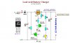
I have been investigating possible DC-UPS charger circuit solutions for my application. I have a simple solution using 2 diodes and a resistor (attached). I have also come across a BQ24702 chip from TI that has all types of bells and whistles.

My application requires the DC-UPS to charge SLA batteries only. The simple circuit provides this functionality and time to charge battery is acceptable (ramps down charge current to trickle at 13.8V).

If all I am interested in is backup and charging is there any reason to explore the TI chip or similar chips. The solution just seems too simple and I want to make sure that the other multifunction chips are overkills for my application.
 

Attachments

  • Simple DC-UPS.pdf
    2.8 KB · Views: 1,549
  • BQ24703PW.pdf
    518.5 KB · Views: 1,571
I doubt that your posted circuit with 2 diodes will charge the battery to 13.8 as the normal silicone diode has more than a 0.4V drop.
 
I understand the voltage drop (Vf) of a diode is a function of current draw and temperature. Based on test results for my application I am confident this drop is accurate, and if not, the 14.2V source can be bumped up a bit to compensate.
 
Shmedly said:
I understand the voltage drop (Vf) of a diode is a function of current draw and temperature. Based on test results for my application I am confident this drop is accurate, and if not, the 14.2V source can be bumped up a bit to compensate.
Can you tell us what the temperature range is and the AMP/HR rating of your 12V battery?
 
Your simple circuit should work fine. You may have to adjust the current limiting resistor to limit the maximum current draw you can supply the battery when returning from complete discharge, check the battery specs for a safe max charge rate. If you can adjust the source DC voltage to correctly set max trickle voltage that would also be good.

The only thing I might think useful to add would be some kind of battery disconnect (relay or power MOSFET) when the battery has discharged to it's lowest safe value. Deep discharging of batteries is very hard on them and will limit their useful life.

I agree the TI IC chip is much too complex for what your application needs.

Good luck
Lefty
 
hi everyone,
I hope you can help me with this one i will attach a charging circuit from another forum , my question is I am planning to use this one to charge a 12v 12AH cealed battery, now the thing is if it is good to use can I withdraw the devices load in barallel with the battery of the charger through a 12v regulator circuit so that if the electricity would go off I will take power from battery or this will cause a conflict some how?
 

Attachments

  • 12 CHARGER.JPG
    12 CHARGER.JPG
    38.1 KB · Views: 1,198
I'm not quite clear about what you're asking.

This simple charger should be able to power devices whilst the battery is connected with no problem.
 
Status
Not open for further replies.

Latest threads

Back
Top